A characteristic feature of modern heaters produced by domestic and foreign industry is their impressive design.
But is it worth spending money on such beauty if you need to heat, for example, a garage in winter or a country house in inclement weather?
In such an unpretentious environment, you can use a homemade device, which, despite all its unpretentiousness, will perfectly cope with the task.
Moreover, making a heater with your own hands due to the simplicity of its design is not at all difficult. Let's get acquainted with some varieties of these devices and find out how and from what you can make a heater with your own hands at home.
A home craftsman who wants to acquire a homemade “hot water bottle” can choose from several options:
Oil
 It is a container equipped with a tubular electric heater (TEH) and filled with oil.
The main element of the heating element is a spiral made of nichrome or other material with high electrical resistance, which begins to heat up when an electric current is passed through it. The spiral is placed in a copper tube filled with sand.
The oil removes heat from the heating element, distributes it over the surface of the body and, in addition, serves as a heat accumulator (after a power outage, the device continues to heat the surrounding air for some time).
Steam-drip
In its design, a vapor-drip heater is very similar to an oil heater, only water vapor is used as a medium that distributes heat. It is formed from a small amount of water, which is poured into the body.
This solution provides two significant advantages:
- When freezing, the vapor-drip heater will not burst, since water occupies only a small part of its volume.
- Steam is an extremely capacious heat accumulator. More precisely, not so much steam as the evaporation process: it is during the transition from liquid to gaseous state that water accumulates a large amount of thermal energy, which is returned when steam condenses on the walls of the heater.
Having transferred heat to the body of the device, the condensed steam in the form of water flows to the lower part, where the heating element is installed. The power of the heating element and the volume of water are selected in such a way that rupture of the heater by steam pressure is excluded.
Due to the fact that the device body is hermetically sealed, its internal walls do not rust due to high humidity.
Candlestick
 A candle flame is known to emit not only light, but also some heat.
Only it usually evaporates to the ceiling in the form of convective air currents and is “smeared” over the entire area of the room.
Why not place a heat trap above the candle? We will tell you what it is in the next section.
Infrared (IR)
Any substance with a temperature different from absolute zero emits “thermal” electromagnetic waves, which are called infrared.
The intensity of this radiation is directly dependent on the temperature of the substance. Water and oil radiators also emit IR waves, but in very small quantities because their surface is relatively cold.
To turn a metal object into an IR emitter, it is enough to heat it to a red glow temperature. If you use special materials, for example, graphite, then quite noticeable “heat” waves can be achieved at relatively low temperatures.
Knowledge of these subtleties will help us make our own IR heater, which will give us heat directly, that is, without the participation of air as an intermediary.
Other types
Since electricity is not available everywhere, structures running on gas or solid fuel have the right to life. The latter include potbelly stoves.
Requirements for the heating device
 When developing the design of a heater of one type or another, we will adhere to the following rules:
- The device must be absolutely safe.
- The design should be simple enough that it can be assembled with your own hands.
- We will use only parts and materials that can be obtained without the slightest difficulty.
The total cost of a homemade product should be no more than 30% of the cost of a factory-made heater of the same type and power. Otherwise, making the device yourself loses its meaning.
Heater assembly
How to assemble homemade heaters for your home? Let us consider step by step the manufacturing technology of the listed types of heaters:
Oil heater
So, let's look at how to build an oil heater with your own hands. The easiest way to make such a heater is from a water heating radiator that already has ready-made threaded holes. In order for it to occupy a vertical position, the radiator must be attached to a frame welded from angle steel with “skis” or legs.
The heating element can be bought in the store. It must have a temperature regulator.

Making an oil heater from a radiator
The thread in the radiator is unlikely to match the thread of the heating element. In order for the latter to be installed, you need to make an adapter in the form of a bushing with threads cut on the outside and inside. The external one must correspond to the thread of the radiator, the internal one to the thread of the heating element.
Before screwing the adapter into the radiator, wrap sealing material onto its external threads. PTFE tape (the more common name is FUM tape), which can withstand very high temperatures, is best suited for this purpose.
If necessary, a homemade oil heater can be equipped with two heating elements. In this case, they need to be connected in parallel.
The heated oil rises upward due to convection, so heating elements must be located at the very bottom of the device.
Do-it-yourself vapor-drip heater
 This type of heater is assembled similarly to an oil heater. Except for a few differences:
- The heating element must be low-power;
- the body must be stainless, otherwise the homemade vapor-drip heater will not last long;
- Instead of transformer oil, you need to add a small amount of water.
The body can be welded independently in the form of a tubular radiator using stainless steel pipes.
To avoid steam rupture of the housing, install a safety valve on it.
Candlestick
The heat "trap" to be placed above the candle is a set of ceramic flower pots of different sizes nested inside one another. It will be enough to have 3 pieces with a diameter, for example, 15, 10 and 5 cm. The pots are installed upside down.
To assemble the “trap” you will need a stud (threaded rod) with a diameter of 6 to 12 mm, 8 nuts and approximately 20 washers.
Here's what to do:
- A nut is screwed onto the stud on one side, and the largest pot is put on the other side, so that its bottom rests on the screwed nut. To avoid having to drill the bottoms of the pots, it is advisable to buy products with ready-made holes.
- The inside of the pot must be secured with a nut, after which the second pot is inserted into it.
- The third pot is installed in the same way, after which a core is assembled inside it on a pin from the remaining nuts and washers.

Homemade candle heater
The support for the structure can be built from bricks - this is the simplest option. A stand welded from a metal profile will look somewhat more elegant.
The power of a candle heater, depending on the size of the candle, can vary from 15 to 42 W. The trapped heat accumulates in the ceramic and, as it heats up, begins to be emitted in the form of infrared waves.
 How to heat a room if there is no standard 220 volt voltage? - a real salvation in such a situation. Three options for manufacturing the device are discussed on the website.
Read about the advantages and disadvantages of gas heaters for garages.
When choosing a heater, its efficiency plays a significant role. Here we will look at the types of heaters and their energy efficiency.
IR heater
The easiest way is to make a so-called film IR heater with your own hands. You need to do this:
- Prepare a mixture of epoxy glue and graphite powder. The best source of graphite is waste brushes of current collectors of electric vehicles - trolleybuses or trams. The basis of the mixture should be graphite; glue is used only as a binder.
- Next you need to take a sheet of laminated paper plastic with an area of about 1 square. m and apply the prepared mixture on it (on the side with the greatest roughness) in the form of a long strip, wriggling like a “snake”.
- On top of the “snake” you need to glue another sheet of plastic, securing it with the same epoxy glue for reliability.
- From different sides, wire strands with a plug at the end need to be connected to the graphite “snake” using terminals. If desired, you can include some kind of primitive thermostat in the circuit.
- To make it more convenient to use a homemade film IR heater, it should be mounted on a wooden frame, like a painting.

Assembling an infrared heater
Before turning it on, be sure to check the resistance of the graphite emitter and calculate the current that will flow in the circuit. It must be compatible with the wiring capabilities.
DIY gas heater
This device will heat the room both by convection and by infrared radiation.Here's what you'll need to make it:
- gas burner and valve;
- hemispherical household sieve;
- galvanized steel sheet;
- steel mesh.
The device is made according to the following scheme:
- From a sheet of galvanized steel, using metal scissors, you need to cut out two blanks that look like a circle (the diameter should correspond to the diameter of the household sieve) with “ears”.
- You need to bolt a gas burner to one of the blanks on one side. Next, you need to bend the “ears” of this workpiece in the direction opposite to the burner and screw a hemispherical sieve to them so that the burner is inside it. The sieve plays the same role as a heat trap in a candle heater.
- Now you need to take a metal mesh and attach it in the form of a cylinder to the same “ears”, so that the sieve with the burner is inside. Rivets should be used as fasteners. Now the mesh with a round piece attached to it resembles a pan in which the burner and the hemispherical sieve covering it are placed.
- Cover the “pan” with the second piece, bending its “ears” upward. We rivet the upper part of the mesh cylinder to these “ears”.
The heater is ready. All that remains is to connect the hose from the gas supply line to the burner.
Video on the topic
Those who want to make a heater with their own hands are not decreasing: the prices for factory-made autonomous heating devices are not encouraging, and their declared characteristics often turn out to be overpriced compared to the real ones. It is useless to make claims: manufacturers always have an “iron excuse” - the efficiency of heating a room strongly depends on its thermal properties. Cases where it was possible to “squeeze” compensation out of a manufacturer for the consequences of an accident that occurred due to the fault of their product are also rare. True, although it is not prohibited by law to make household heaters yourself, trouble caused by a homemade product will be a serious aggravating circumstance for its manufacturer and owner. Therefore, this article further describes how to correctly design and manufacture safe household heaters of several systems, which are not inferior in thermal efficiency to the best industrial designs.
Constructions
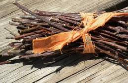
Amateur craftsmen build heaters that are often very intricate in design, see photo in Fig. Sometimes they are done carefully. But overwhelming Most of the homemade heating devices described in RuNet have one thing in common: the high degree of danger they create, harmoniously combined with the complete discrepancy between the expected technical characteristics and the actual ones. First of all, this relates to reliability, durability and transportability.

Make a heater for your home. premises or a camping autonomous one for summer cottages, tourism and fishing, the following systems are possible (from left to right in the figure):
- With direct air heating using natural convection - an electric fireplace.
- With forced blowing of the heater - fan heater.
- With indirect air heating, natural convection or forced air flow - oil or water-air heater.
- In the form of a surface emitting thermal (infrared, IR) rays - a thermal panel.
- Fiery autonomous.
The latter differs from a stove, stove or hot water boiler in that most often it does not have a built-in burner/furnace, but uses waste heat from heating and cooking appliances. However, the line here is very blurred: gas heaters with a built-in burner are commercially available and can be made independently. Many of them can be used to cook or reheat food. Here, at the end, a flame heater will also be described, which is not wood-based, not liquid fuel, not gas-based, and certainly not a stove. And the others are considered in descending order of their degree of safety and reliability. Which, nevertheless, with proper execution and in the “worst” samples, fully comply with the requirements for household autonomous heating devices.
Thermal panel
This is quite complex and labor-intensive, but the safest and most effective type of household electric heater: a double-sided thermal panel for 400 W in a 12 sq. m room. m in a concrete house heats from +15 to +18 degrees. The required power of the electric fireplace in this case is 1200-1300 W. The cost of making a thermal panel yourself is small. Thermal panels work in the so-called. far (more distant from the red region of the visible spectrum) or long-wave IR, so the heat is soft, not burning. Due to the relatively weak heating of the heat-emitting elements, if they are made correctly (see below), the operational wear of thermal panels is practically absent, and their durability and reliability are limited by unforeseen external influences.
The heat-emitting element (emitter) of a thermal panel consists of a thin flat conductor made of a material with high electrical resistivity, sandwiched between 2 plates - dielectric plates transparent to IR. Thermal panel heaters are made using thin-film technology, and the covers are made from a special plastic composite. Both are unavailable at home, so many hobbyists are trying to make heat emitters based on a carbon coating sandwiched between 2 glasses (item 1 in the figure below); ordinary silicate glass is almost transparent to IR.
This technical solution is a typical surrogate, unreliable and short-lived. The conductive film is obtained either from candle soot or by spreading an epoxy compound filled with ground graphite or electrical carbon onto the glass. The main drawback of both methods is the uneven film thickness. Carbon in the amorphous (coal) or graphitic allotropic modification is a semiconductor with high intrinsic conductivity for this class of substances. The effects characteristic of semiconductors appear in it weakly, almost imperceptibly. But with increasing temperature of the conductive layer, the electrical resistivity of the carbon film does not increase linearly, like that of metals. The consequence is that thin areas heat up more and burn out. The current density in the thicker ones increases, they heat up, they also burn out, and soon the entire film burns out. This is the so-called. avalanche burnout.
In addition, the soot film is very unstable and quickly crumbles on its own. To obtain the required heater power, up to 2 volumes of carbon filler must be added to the epoxy glue. In fact, up to 3 is possible, and if you add 5-10% by volume of a plasticizer - dibutyl phthalate - to the resin before adding the hardener, then up to 5 volumes of filler. But the ready-to-use (not hardened) compound turns out to be thick and viscous, like plasticine or fatty clay, and it is unrealistic to apply it with a thin film - epoxy sticks to everything in the world except paraffin hydrocarbons and fluoroplastic. You can make a spatula out of the latter, but the compound behind it will stretch out in clumps and lumps.
Finally, graphite and coal dust are very harmful to health (have you heard about silicosis in miners?) and extremely dirty substances. It is impossible to remove or wash away their traces; soiled things have to be thrown away, they stain others. Anyone who has ever dealt with graphite lubricant (this is the same finely crushed graphite) - as they say, I will live, I will not forget. That is, homemade emitters for thermal panels need to be made in some other way. Fortunately, calculations show that the “good old”, proven over many decades and inexpensive nichrome wire is suitable for this.
Calculation
Through 3-mm window glass, approx. 8.5 W/sq. dm IR. From the “pie” of the thermal panel emitter, 17 W will go in both directions. Let's set the dimensions of the emitter to 10x7 cm (0.7 sq. dm); such pieces can be cut from culls and cutting waste in almost unlimited quantities. Then one emitter will give us a room of 11.9 W.
Let's take the heater power to be 500 W (see above). Then you will need 500/11.9 = 42.01 or 42 emitters. Structurally, the panel will consist of a matrix of 6x7 emitters with dimensions without frames of 600x490 mm. Let's put it on a frame up to 750x550 mm - ergonomically it works, it's quite compact.
The current consumed from the network is 500 W/220 V = 2.27 A. The electrical resistance of the entire heater is 220 V/2.27 A = 96.97 or 97 Ohms (Ohm’s law). The resistance of one emitter is 97 Ohm/42 = 2.31 Ohm. The resistivity of nichrome is almost exactly 1.0 (Ohm * sq. mm)/m, but what cross-section and length of wire is needed for one emitter? Will the nichrome “snake” (item 2 in the figure) fit between 10x7 cm glass?

Current density in open, i.e. in contact with air, nichrome electric spirals - 12-18 A/sq. mm. They glow from dark to light red (600-800 degrees Celsius). Let's take 700 degrees at a current density of 16 A/sq. mm. Under the condition of free IR radiation, the temperature of nichrome depends on the current density approximately by the square root. Let's reduce it by half, to 8 A/sq. mm, we get the operating temperature of nichrome at 700/(2^2) = 175 degrees, safe for silicate glass. The temperature of the outer surface of the emitter (without taking into account heat removal due to convection) will not exceed 70 degrees with an outer surface of 20 degrees - it is suitable both for heat transfer by “soft” IR and for safety if you cover the emitting surfaces with a protective mesh (see below).
A rated operating current of 2.27 A will give a nichrome cross section of 2.27/8 = 0.28375 sq. mm. Using the school formula for the area of a circle, we find the diameter of the wire - 0.601 or 0.6 mm. Let us take it with a margin of 0.7 mm, then the heater power will be 460 W, because it depends on its operating current squared. 460 W is enough for heating; 400 W would be enough, and the durability of the device will increase several times.
1 m of nichrome wire with a diameter of 0.7 mm has a resistance of 2.041 Ohms (0.7 squared = 0.49; 1/0.49 = 2.0408...). To obtain a resistance of one emitter of 2.31 Ohms, you will need 2.31/2.041 = 1.132... or 1.13 m of wire. Let's take the width of the nichrome “snake” to be 5 cm (1 cm of margin at the edges). Add 2.5 mm per turn of 1 mm nails (see below), for a total of 5.25 cm per snake branch. The branches will be needed 113 cm/5.25 cm = 21.52..., let's take 21.5 branches. Their total width is 22x0.07 cm (wire diameter) = 1.54 cm. Let's take the length of the snake to be 8 cm (1 cm of margin from the short edges), then the wire laying coefficient is 1.54/8 = 0.1925. In the lousiest Chinese low-power power transformers it is approx. 0.25, i.e. We have plenty of space for the bends and gaps between the branches of the snake. Phew, the fundamental issues have been resolved, we can move on to R&D (experimental design work) and technical design.
OCD
The thermal conductivity and transparency of IR silicate glass vary greatly from brand to brand and from batch to batch. Therefore, first you will need to make 1 (one) emitter, see below, and test it. Depending on their results, you may have to change the diameter of the wire, so do not buy a lot of nichrome at once. In this case, the rated current and power of the heater will change:
- Wire 0.5 mm – 1.6 A, 350 W.
- Wire 0.6 mm - 1.9 A, 420 W.
- Wire 0.7 mm - 2.27 A, 500 W.
- Wire 0.8 mm - 2.4 A, 530 W.
- Wire 0.9 mm - 2.6 A, 570 W.
Note: who is literate in electricity - the rated current, as you can see, does not change according to the square of the wire diameter. Why? On the one hand, thin wires have a relatively large radiating surface. On the other hand, with a thick wire, the permissible IR power transmitted by the glass cannot be exceeded.
For testing, the finished sample is installed vertically, supported by something non-flammable and heat-resistant, on a fireproof surface. Then the rated current is supplied to it from an regulated power supply (PS) of 3 A or more or LATP. In the latter case, the sample cannot be left unattended during the entire test! The current is controlled by a digital tester, the probes of which must be tightly compressed with the current-carrying wires using a screw with a nut and washers. If the prototype is powered by LATR, the tester must measure the AC current (limit AC 3A or AC 5A).
First of all, you need to check how the glass behaves. If it overheats and cracks within 20-30 minutes, then the entire batch may be unusable. For example, dust and dirt become embedded in used glass over time. Cutting them is sheer agony and the death of a diamond glass cutter. And such glass cracks at much lower heat than new glass of the same type.
Then, after 1-1.5 hours, the strength of the IR radiation is checked. The temperature of the glass is not an indicator here, because... The main part of the IR is emitted by nichrome. Since you most likely will not have a photometer with an IR filter, you will have to check it with your palms: they are held parallel to the emitting surfaces at a distance of approx. 15 cm from them for at least 3 minutes. Then, for 5-10 minutes, you should feel even, soft warmth. If the IR from the emitter begins to burn the skin immediately, reduce the diameter of the nichrome. If after 15-20 minutes you don’t feel a slight burning sensation (as in the sun in the middle of summer), you need to take thicker nichrome.
How to bend a snake
The design of the emitter of a homemade panel heater is shown in pos. 2 fig. higher; The nichrome snake is shown conditionally. Glass plates cut to size are cleaned of dirt and washed with a brush in water with the addition of any dishwashing detergent, then also washed with a brush under running clean water. “Ears” - contact lamellas measuring 25x50 mm made of copper foil - are glued to one of the covers with epoxy glue or instant cyanoacrylate (superglue). The overlap of the “ear” on the lining is 5 mm; 20 mm sticks out. To prevent the lamella from falling off before the glue has set, place something 3 mm thick (the thickness of the lining glass) under it.
Next you need to form the snake itself from nichrome wire. This is done on a mandrel template, the diagram of which is given in pos. 3, and a detailed drawing is in Fig. Here. The “tails” for annealing the snake (see below) should be given at least 5 cm. The bitten ends of the nails are sanded to roundness on an emery stone, otherwise it will be impossible to remove the finished snake without crushing it.

Nichrome is quite elastic, so the wire wound on the template must be annealed so that the snake holds its shape. This should be done in semi-darkness or low light. The snake is supplied with a voltage of 5-6 V from a power supply of at least 3 A (this is why a fireproof lining is needed on a tree). When the nichrome glows cherry, turn off the current, allow the thread to cool completely, and repeat this procedure 3-4 times.
The next step is to press the snake with your fingers through the plywood strip placed on it and carefully unwind the tails wound on 2-mm nails. Each tail is straightened and shaped: a quarter of a turn remains on a 2-mm nail, and the rest is cut flush with the edge of the template. The remainder of the “tail” of 5 mm is cleaned with a sharp knife.
Now the snake needs to be removed from the mandrel without damaging it, and secured to the substrate, ensuring reliable electrical contact of the leads with the lamellas. Remove with a pair of knives: their blades are slipped from the outside under the bends of the branches on 1-mm nails, carefully pry up and lift the crimped thread of the heater. Then the snake is placed on the substrate and the leads are bent a little, if necessary, so that they lie approx. in the middle of the slats.
Nichrome cannot be soldered with metal solders with inactive flux, and the remaining active flux can corrode the contact over time. Therefore, nichrome is “soldered” to copper, so-called. liquid solder - conductive paste; It is sold in radio stores. A drop of liquid solder is squeezed onto the contact of the stripped nichrome with copper and pressed with a finger through a piece of plastic film so that the paste does not stick out upward from the wire. You can immediately press it down with some flat weight instead of your finger. Remove the weight and film after the paste has hardened, from an hour to a day (the time is indicated on the tube).
The “solder” has frozen – it’s time to assemble the emitter. Along the middle we squeeze a thin, no thicker than 1.5 mm, “sausage” of ordinary construction silicone sealant onto the snake, this will prevent the wire bends from slipping and closing. After this, we squeeze out the same sealant with a thicker roller, 3-4 mm, along the contour of the substrate, retreating from the edge of approx. by 5 mm. We apply a cover glass and very carefully so that it does not slide to the side and pull the snake along with it, press down until it fits tightly, and set the emitter aside to dry.
The drying rate of silicone is 2 mm per day, but after 3-4 days, as it may seem, it is still impossible to take the emitter into work further; you need to let the inner roller that fixes the bends dry. You will need approx. a week. If many emitters are made for a working heater, they can be dried in a stack. The bottom layer is laid out on plastic film, and covered with it on top. Elements following. layers are laid across the underlying ones, etc., separating the layers with film. The stack, for guarantee, takes 2 weeks to dry. After drying, the protruding excess silicone is cut off with a safety razor blade or a sharp mounting knife. Silicone deposits must also be completely removed from the contact lamellas, see below!
Installation
While the emitters are drying, we make 2 identical frames from slats of hard wood (oak, beech, hornbeam) (item 4 in the figure with the diagram of the panel heater). The connections are made by cutting into half the wood and fastened with small self-tapping screws. MFD, plywood and wood materials with synthetic binders (chipboard, OSB) are not suitable, because prolonged heating, even if not strong, is strictly contraindicated for them. If you have the opportunity to cut frame parts from textolite or fiberglass, that’s generally great, but ebonite, bakelite, textolite, carbolite and thermoplastic plastics are not suitable. Before assembly, wooden parts are impregnated twice with a water-polymer emulsion or water-based acrylic varnish diluted in half.
Ready-made emitters are placed in one of the frames (item 5). The overlapping lamellas are electrically connected by drops of liquid solder, as are the jumpers on the sidewalls, forming a series connection of all emitters. It is better to solder the supply wires (from 0.75 sq. mm) with ordinary low-melting solder (for example, POS-61) with inactive flux paste (composition: rosin, ethyl alcohol, lanolin, see on the bottle or tube). Soldering iron - 60-80 W, but you need to solder quickly so that the emitter does not come unglued.
The next step at this stage is to apply a second frame and mark on it where the supply wires are located; grooves will need to be cut for them. After this, we assemble the frame with the emitters using small screws, pos. 6. Take a closer look at the location of the fastening points: they should not fall on live parts, otherwise the fastening heads will be energized! Also, in order to prevent accidental contact with the edges of the lamellas, all ends of the panel are covered with non-flammable plastic with a thickness of 1 mm, for example. PVC filled with chalk from cable channels (ducts for wiring). For the same purpose, and for greater structural strength, silicone sealant is applied to all joints of the glass and frame parts.
The final steps are firstly the installation of legs with a height of 100 mm. A sketch of the wooden leg of a panel heater is given in pos. 7. The second is to apply a protective steel mesh made of thin wire with a mesh size of 3-5 mm to the sidewalls of the panel. Third, the cable entry is designed with a plastic box: it houses contact terminals and a light indicator. Possibly a thyristor voltage regulator and a protective thermal relay. That's it, you can turn it on and warm up.
Thermal painting
If the power of the described thermal panel does not exceed 350 W, a picture heater can be made from it. To do this, foil insulation is applied to the back side, the same one that is used for thermal insulation. Its foil side should be facing the panel, and the porous plastic side should be facing out. The front side of the heater is decorated with a fragment of photo wallpaper on plastic; thin plastic is not such an obstacle for IR. In order for the picture-heater to warm better, you need to hang it on the wall at an angle of approx. 20 degrees.
What about foil?
As you can see, a homemade panel heater is quite labor-intensive. Is it possible to simplify the work by using, say, aluminum foil instead of nichrome? The thickness of the baking sleeve foil is approx. 0.1 mm, seems to be a thin film. No, the point here is not the thickness of the film, but the resistivity of its material. For aluminum it is low, 0.028 (Ohm * sq. mm)/m. Without giving detailed (and very boring) calculations, we will indicate their result: the area of a thermal panel with a power of 500 W on an aluminum film 0.1 mm thick turns out to be almost 4 square meters. m. Still, the film turned out to be a bit thick.
12 V
A homemade fan heater can be quite safe in a low-voltage, 12 V version. You cannot get more than 150-200 W of power from it; it will need a step-down transformer or power supply that is too large, heavy and expensive. However, 100-120 W is just enough to keep a small plus in the basement or cellar all winter, which guarantees against frozen vegetables and cans of homemade products bursting from frost, and 12 V is the voltage permissible in rooms with any degree of danger of electric shock. You cannot put more in the basement/cellar, because... According to electrical engineering classification, they are especially dangerous.
The basis of the 12 V fan heater is an ordinary red working hollow (hollow) brick. A one and a half thickness of 88 mm (top left in the figure) is best suited, but a double thickness of 125 mm (bottom) will also work. The main thing is that the voids are through and identical.

The design of a 12 V “brick” fan heater for the basement is shown there in Fig. Let's count the nichrome heating coils for it. We take a power of 120 W, this is with some margin. Current, respectively, 10 A, heater resistance 1.2 Ohm. On the one hand, the spirals are blown. On the other hand, this heater must operate unattended for a long time in rather difficult conditions. Therefore, it is better to connect all the spirals in parallel: one will burn out, the rest will be pulled out. And it’s convenient to regulate the power - just turn off 1-2 or several coils.
There are 24 channels in a hollow brick. The spiral current of each channel is 10/24 = 0.42 A. Not enough, nichrome is needed very thin and, therefore, unreliable. This option would be suitable for a household fan heater up to 1 kW or more. Then the heater must be calculated, as described above, for a current density of 12-15 A/sq. mm, and divide the resulting wire length by 24. To each segment, 20 cm are added into 10-cm connecting “tails”, and the middle is twisted into a spiral with a diameter of 15-25 mm. With "tails" all the spirals are connected in series using clamps made of copper foil: its tape 30-35 mm wide is wound in 2-3 layers onto folded nichrome wires and twisted into 3-5 turns with a pair of small pliers. To power the fans, you will have to install a low-power 12 V transformer. This heater is well suited for a garage or warming up a car before a trip: like all fan heaters, it quickly warms up the middle of the room, without wasting heat on heat loss through the walls.
Note: Computer fans are often called coolers (literally – coolers). In fact, a cooler is a cooling device. For example, a processor cooler is a finned radiator in a block with a fan. And the fan itself is also a fan in America.
But let's go back to the basement. Let's see how much nichrome is needed for a reduced to 10 A/sq. mm for reliability reasons current density. The wire cross-section is clear without calculations - 1 sq. mm. Diameter, see calculations above – 1.3 mm. Such nichrome is on sale without difficulty. The required length for a resistance of 1.2 Ohm is 1.2 m. What is the total length of the channels in the brick? We take one and a half thickness (weighs less), 0.088 m. 0.088x24 = 2.188. So we just need to thread a piece of nichrome through the voids of the brick. It’s possible through one, because According to the calculation, 1.2/0.088 = 13.(67) channels are needed, i.e. 14 is enough. So they heated the basement. And quite reliably - such thick nichrome and strong acid will not quickly corrode.
Note: the brick in the body is fixed with small steel corners on bolts. An automatic protective device must be included in the powerful 12 V circuit, e.g. automatic plug for 25 A. Inexpensive and quite reliable.
IP and UPS
It is better to take (make) an iron transformer for heating a basement with powerful winding taps of 6, 9, 12, 15 and 18 V, this will allow you to regulate the heating power within a wide range. 1.2 mm nichrome with blowing will pull 25-30 A. To power the fans, then you need a separate 12 V 0.5 A winding and also a separate cable with thin wires. To power the heater, cores of 3.5 sq.m. are required. mm. A powerful cable can be the crappiest - PUNP, KG, for 12 V there is no fear of leaks and breakdown.
Maybe you don’t have the opportunity to use a step-down transformer, but you have a switching power supply (UPS) from an unusable computer lying around. Its 5 V channel is enough power; standard - 5 V 20 A. Then, firstly, you need to recalculate the heater to 5 V and the power of 85-90 W so as not to overload the UPS (the wire diameter is 1.8 mm; the length is the same). Secondly, to supply 5 V, you need to connect together all the red wires (+5 V) and the same number of black wires (common GND wire). 12 V for fans is taken from any yellow wire (+12 V) and any black. Thirdly, you need to short-circuit the PC-ON logical start circuit to the common wire, otherwise the UPS simply will not turn on. Usually the PC-ON wire is green, but you need to check: remove the casing from the UPS and look at the markings on the board, on top or on the mounting side.
heating elements
For heaters: types you will have to buy heating elements: 220 V electrical appliances with open heaters are extremely dangerous. Here, pardon the expression, you need to think first of all about your own skin and property, whether there is a formal ban or not. It’s easier with 12-volt devices: according to statistics, the degree of danger decreases in proportion to the square of the supply voltage ratio.
If you already have an electric fireplace, but it doesn’t heat well, it makes sense to replace a simple air heating element with a smooth surface (pos. 1 in the figure) with a finned one, pos. 2. The nature of convection will then change significantly (see below) and heating will improve when the power of the finned heating element is 80-85% of the smooth one.

A cartridge heating element in a stainless steel housing (item 3) can heat both water and oil in a tank made of any structural material. If you buy one, be sure to check that the kit includes gaskets made of oil-heat-gasoline-resistant rubber or silicone.
A copper water heating element for a boiler is equipped with a tube for a temperature sensor and a magnesium protector, pos. 4, which is good. But they can only heat water and only in a stainless steel or enameled tank. The heat capacity of oil is much less than that of water, and the body of a copper heating element in oil will soon burn out. The consequences are severe and fatal. If the tank is made of aluminum or ordinary structural steel, then electrocorrosion due to the presence of a contact potential difference between the metals will very quickly eat away the protector, and then eat through the body of the heating element.
T. called. dry heating elements (item 5), like cartridge ones, are capable of heating both oil and water without additional protective measures. In addition, their heating element can be changed without opening the tank and without draining the liquid from there. There is only one drawback - they are very expensive.
Fireplace

You can improve an ordinary electric fireplace, or make your own efficient one based on a purchased heating element, using an additional casing that creates a secondary convection circuit. From a conventional electric fireplace, firstly, the air flows upward in a rather hot but weak stream. It quickly reaches the ceiling and through it warms more of the neighbors' floors, attic or roof than the owner's room. Secondly, the IR coming down from the heating element in the same way warms the neighbors below, the subfloor or basement.
In the design shown in Fig. on the right, downward IR is reflected into the outer casing and heats the air in it. The thrust is further enhanced by the suction of hot air from the inner casing, which is less heated from the outer casing at the narrowing of the latter. As a result, the air from an electric fireplace with a double convection circuit comes out in a wide, moderately heated stream, spreads to the sides without reaching the ceiling, and effectively heats the room.
Oil and water
The effect described above is also produced by oil and water-air heaters, which is why they are popular. Industrially produced oil heaters are made hermetically sealed with a permanent filling, but it is in no case recommended to repeat them yourself. Without an accurate calculation of the volume of the housing, internal convection in it and the degree of oil filling, a rupture of the housing, an electrical failure, oil spillage and fire are possible. Underfilling is just as dangerous as overfilling: in the latter case, the oil simply tears the housing under pressure when heated, and in the former, it first boils. If you make the housing of a deliberately larger volume, then the heater will heat disproportionately weakly compared to the electricity consumption.
In amateur conditions, it is possible to build an open-type oil or water-air heater with an expansion tank. The diagram of its device is shown in Fig. Once upon a time they made quite a lot of these, for garages. The air from the radiator is slightly heated, the temperature difference between inside and outside is kept minimal, which is why heat loss is reduced. But with the advent of panel heaters, oil-based homemade products are disappearing: thermal panels are better in all respects and are quite safe.

If you still decide to make your own oil heater, keep in mind that it must be reliably grounded, and you only need to fill it with very expensive transformer oil. Any liquid oil gradually bituminizes. Increasing temperature accelerates this process. Motor oils are designed to allow oil to circulate among moving parts due to vibration. Bituminous particles in it form a suspension that only pollutes the oil, which is why it has to be changed from time to time. In the heater, nothing will prevent them from depositing carbon deposits on the heating element and in the tubes, causing the heating element to overheat. If it bursts, the consequences of oil heater accidents are almost always very severe. Transformer oil is expensive because the bituminous particles in it do not settle into soot. There are few sources of raw materials for mineral transformer oil in the world, and the cost of synthetic oil is high.
Fiery
Powerful gas heaters for large rooms with catalytic afterburning are expensive, but record-breakingly economical and efficient. It is impossible to reproduce them under amateur conditions: you need a micro-perforated ceramic plate with platinum coating in the pores and a special burner made of parts made with precision precision. At retail, one or the other will cost more than a new heater with a warranty.

Tourists, hunters and fishermen have long come up with low-power afterburner heaters in the form of an attachment to a camp stove. These are also produced on an industrial scale, pos. 1 in Fig. Their efficiency is not so great, but it’s enough to heat the tent until lights out in sleeping bags. The design of the afterburner is quite complex (item 2), which is why factory tent heaters are not cheap. Fans also make a lot of these, from cans or, for example. from automobile oil filters. In this case, the heater can operate both from a gas flame and from a candle, see video:
Video: Portable oil filter heaters
With the advent of heat-resistant and heat-resistant steels in widespread use, lovers of being outdoors are increasingly giving preference to gas camping heaters with afterburning on a grid, pos. 3 and 4 - they are more economical and heat better. And again, amateur creativity combined both options into a combined type mini-heater, pos. 5., capable of working from both a gas burner and a candle.

A drawing of a homemade mini-heater with afterburning is shown in Fig. on right. If it is used occasionally or temporarily, it can be made entirely from tin cans. For an enlarged version for the garden, cans of tomato paste, etc. will be used. Replacing the perforated mesh cover significantly reduces warm-up time and fuel consumption. A larger and very durable version can be assembled from car wheels, see next. video clip. This is already considered a stove, because... You can cook on it.
Video: heater-stove made from a wheel rim
From a candle
A candle, by the way, is a fairly strong source of heat. For a long time, this property was considered a hindrance: in the old days, at balls, ladies and gentlemen would sweat, makeup would run, and powder would clump together. How they even turned cupids after that, without hot running water and a shower, is difficult for a modern person to understand.

The heat from a candle in a cold room is wasted for the same reason that a single-circuit convection heater does not heat well: hot exhaust gases rise up too quickly and cool, producing soot. Meanwhile, making them burn out and give heat is easier than a gas flame, see fig. In this system, a 3-circuit afterburner is assembled from ceramic flower pots; baked clay is a good IR emitter. A candle heater is intended for local heating, say, so as not to tremble while sitting at the computer, but just one candle provides a surprising amount of heat. When using it, you only need to open the window slightly, and when going to bed, be sure to extinguish the candle: it also consumes a lot of oxygen for combustion.
Until recently, infrared heaters were a curiosity. Now they are becoming common devices that are used everywhere: at home, in the country, in production workshops and even in open areas. It has gotten to the point that many “Kulibins”, having frozen in the garage, use improvised materials to make an infrared heater with their own hands. Below we will look at several ways to make IR from improvised materials.
Unlike other types of heaters, IR does not heat the air in the room. It works on the principle of our luminary: heats up objects that get in the way of infrared radiation. And heated surfaces share heat with the surrounding air.
An infrared heater consists of two main elements:
- heating element-emitter;
- reflector (reflector).
Both of these elements are assembled in a heat-resistant housing.
The reflector is made from aluminum or polished steel. The reflector's task is to generate a radiation flux and direct it to the desired area.
Lamps are used as a heating element (emitter):
- halogen;
- carbon and quartz.
Heaters with halogen lamps are cheaper than those with carbon or quartz lamps. But they have one drawback that does not favor the use of the device in residential premises: their operation is accompanied by the glow of a lamp. Agree that you can’t put such a heater in the bedroom, or in the nursery either. Although, on balconies and loggias, if they are not combined with the main room, it is possible.
Unlike halogen lamps, carbon and quartz lamps do not produce light (but their price is higher). Actually, this is their only difference from halogen lamps. Some sellers claim that carbon and quartz, in addition to heating the room, also improve the health of residents. Such statements should not be taken seriously: doctors clearly state that infrared heaters do not have any effect on human health.
In addition to the emitter and reflector, the heater design contains a fire hazard sensor and thermostats. The first ones automatically turn off the heater when it overheats or tips over, the second ones serve to maintain the set temperature.
Making your own infrared heater
IR heater from an old reflector
You will need:
- Soviet-made reflector;
- nichrome thread;
- steel rod;
- fireproof dielectric.
Tip: As a dielectric, you can use a plate of any diameter made of glazed ceramic.
Your actions:
- thoroughly clean the reflector reflector from dirt and dust;
- check the integrity of the power cord, plug, connection to the terminals for connecting the spiral;
- measure the length of the spiral wound onto the ceramic cone of the device;
- take a steel rod of the same length and thread a nichrome thread onto it. Winding pitch – 2 mm;
- upon completion of winding, remove the spiral from the rod;
- lay the spiral in a free state (its turns should not touch) on a fire-resistant dielectric;
- connect the current from the power outlet to the ends of the spiral;
- turn off the heated coil and place it in the groove of the ceramic heater cone;
- connect it to the power terminals.
Made from glass and foil
Necessary materials:
- glass: two pieces of the same size;
- aluminum foil;
- sealant;
- paraffin candle;
- power cord with plug;
- epoxy glue;
- cotton buds;
- clean cotton napkin;
- candle holder.

What we do:
- remove dust, dirt, grease, traces of paint, if any, etc. from the surface of the glass;
- light the candle and smoothly move the glass plates over its flame (alternately and only on one side). As a result of this operation, a uniform layer of soot should form on the glass. It will serve as a conductor in the heater;
Tip: If the glass is cooled before processing, the layer of soot will lie more evenly on its surface.
- Using cotton swabs, we form a transparent “frame” about five millimeters wide around the perimeter of the glass;
- Cut out two rectangles from a sheet of aluminum foil. Their width should be equal to the width of the conductive layer (the very soot that you diligently deposited on the glass at the beginning of work). The foil strips in our IR will act as electrodes;
- place the glass plate with the smoked side up and apply epoxy glue to its surface;
- We place foil on the edges of the plate so that their ends extend beyond the glass;
- carefully cover the resulting structure with a second glass plate (smoky side inward) and glue the “pie” together, carefully pressing its layers together;
- We seal the perimeter of the structure;
- measure the resistance of the conductive layer;
- Using the obtained result, we calculate the heater power using the formula:
N = R x I 2, where
N – power (W);
R – resistance (Ohm);
I - current strength (A).

If everything went well and the power did not exceed the value allowed by regulations, you can connect the homemade infrared heater to the outlet. If you don’t guess correctly, disassemble the device and start all over again.
Note: For orientation, keep in mind that the wider the soot strip, the lower the resistance. Consequently, the heating temperature of the glass will be higher.
IR based on laminated plastic
You will need:
- paper laminate with an area of 1 square. m – 2 blanks;
- epoxy glue;
- copper busbar for making terminals;
- wood for making a frame;
- power cord with plug.
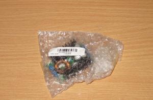
Graphite can be “mined” from batteries that have expired.
What need to do:
 Graphite for heater
 - mix epoxy glue with graphite until a thick mass is obtained (this prepares a future conductor with high resistance);
- Place the plastic blank on the workbench with the rough side up;
- Apply an epoxy-graphite mixture to the surface of the plastic using zigzag strokes;
- similarly prepare the second plate;
- We place the plates on top of each other with the treated sides facing each other and glue them together;
- We attach copper terminals on opposite sides of the graphite conductor;
- We construct a fixing wooden frame along the perimeter of the structure;
- leave the product alone until the graphite-epoxy layer has completely dried;
- we measure the conductor resistance and calculate the power (see option 2).
The resistance value of the conductor depends on the amount of graphite in the mass. If, as a result of testing, it turns out that the conductor resistance is too low, prepare a new epoxy-graphite composition by increasing the dose of graphite. Accordingly, high resistance can be reduced by reducing the amount of graphite powder in the conductor.
After you achieve a positive result, you can connect the power cord to the terminals and plug the device into the outlet. You can improve the design by installing a simple thermostat.
We have considered only a small fraction of the methods for making infrared heaters. In fact, there are a great many options, because home craftsmen tend to use different things that have served their purpose. Their diversity determines the number of inventions of homemade infrared heaters.
Have you decided to build a homemade heater for your home or garage, but don’t know how? I bring to your attention 4 simple ideas for making an electric fireplace, a heat gun, a candle stove and an infrared burner. I will tell you how to assemble such a heater in 1 hour.
What can be made from scrap materials

Anyone can make an electric heater with their own hands, even without being a professional electrician. Let's look at two step-by-step instructions for assembling a heat gun and a spiral fireplace.
Idea one - assembling an electric spiral fireplace
Such a fireplace will be a good solution for heating rooms with a small area. For example, by making an electric heater with your own hands, you can heat your home workshop or office.
| Illustration | Materials and tools, and their description |
 |
Solid stove brick. One ceramic brick will be used as a dielectric body for winding the spiral. Two bricks will be used as heat dissipators. |
 |
Tungsten or nichrome wire. Wire made of refractory alloys is needed for winding the spiral. For normal heating, we use wire with a diameter of at least 0.5 mm.
|
 |
Metal strip. A strip of steel 20-30 mm wide and 3 mm thick is needed to make a reinforcing frame for the structure. |
 |
Grinder with cutting disc for concrete. We will use a grinder for cutting bricks, and therefore a regular metal disc will not work. |
 |
Welding machine. During installation, you will have to weld the metal strip. If you have no experience with welding, you can use a bolted connection. |
| Illustrations | Description of actions |
 |
We make notches.
|
 |
Making a heating element. Previously prepared nichrome or tungsten wire is wound over the brick, held in the notches. |
 |
Manufacturing of heat accumulating surfaces.
|
 |
Installing the feet.
|
 |
Manufacturing of protective housing. The heater is almost ready, but to make it safe to use, we assemble a pipe with a rectangular cross-section from tin. The assembled pipe should be 2-3 cm wider than the brick structure.
|
 |
Installation of the protective housing. We install the protective casing on top of the bricks, so that the same gap is maintained between them and the tin on all sides. To do this, you may have to weld additional spacers from a metal strip. |
 |
Wiring connection and test run. A wire with a plug is connected to the two ends of the spiral, through connecting terminals or by twisting. Before test switching on, inspect the entire structure and make sure that the turns of the homemade spiral do not touch. After this, the design can be connected to the network and tested in operation. |
Idea two - assembling a heat gun from a bucket and a twisted coil

To make such a heater, you will need a metal bucket, a large built-in fan and a coil from an old electric stove. For assembly, ordinary tools that are likely to be found in any home workshop will be sufficient.
The table provides simple installation instructions.
| Illustration | Description of actions |
 |
Separate the bottom. We separate the bottom from the prepared bucket so that we get a cylinder without a bottom and without a top. |
 |
Preparing the spiral. We cut a square metal lattice to the size of the bucket. We lay the spiral along the grid so that the diameter of its layout is slightly smaller than the internal diameter of the bucket. |
 |
Installation of the spiral. In the prepared bucket we make slits into which we insert the corners of the grate. As a result, the grid with a spiral should be located 30 mm from the edge of the bucket. |
 |
Wiring connection and switch installation. We bring the wires out from the spiral. For safety, we route the wiring through insulators. Here, on the side of the bucket, we install an insulated block of automatic machines. |
 |
Fan installation. On the opposite side of the grille with a spiral, install a fan. We attach the fan to the walls of the bucket with self-tapping screws and connect it to the machines. |
 |
Installation of supports. As shown in the photo, we drill through holes along the edges of the bucket. We thread pins through the holes and secure them with nuts. As a result, the structure should not sway and should be stable. |
 |
Trial run. We turn on the gun into the network and first start the fan. Then turn on the power to the coil. |
Idea three - making a microstove using an alcohol lamp or candle

Yes, this is not a typo - such a stove takes up little space, and an ordinary candle or alcohol lamp is used as fuel for intensive heating!

To make a heating device, you will need two clay pots of different sizes and an alcohol lamp. The tools you will need are a drill with a pobedit bit, a pencil and a ruler. So let's get to work.
| Illustration | Description of actions |
 |
Making markings on a small pot. From the center of the bottom of the pot we mark a line that will divide the bottom in half. Now, relative to the line that has already been drawn, we draw a transverse line to make a cross. From these lines we move to the walls and, as shown in the photo, mark a point on each side. Each point should deviate from the bottom by 20 mm. |
 |
Drilling holes. According to the markings made, one hole needs to be drilled on each side of the pot. That is, there should be four holes.
|
 |
Preparing a large pot. Similarly, drill two holes in a large pot. But the holes in a large pot should not be located near the bottom, but along the edge. |
 |
Lighting the fuel. Fill the alcohol lamp with alcohol or similar liquid fuel. Place the alcohol lamp on the stand and light it.
|
 |
Installing the first pot. After the alcohol lamp flares up, place a large pot on top of it. We do this so that the flame from the alcohol lamp is knocked out of the hole for water drainage. We wait 5 minutes until the moisture collected by the ceramics during drilling has completely evaporated. |
 |
Installing the second pot. Place a small pot on top of the already dry large pot. The location of the holes relative to each other is not important, since they are needed for traction and provide it, even if they do not coincide. |
Answers to questions about using the heater

How hot and for how long does it heat? If the stove is assembled correctly, the heat obtained from a spirit lamp or a candle is enough to heat a small room for half an hour. The fuel in the alcohol stove burns within 15-20 minutes, heating the ceramic pots and the air underneath them to a high temperature.
After this, within 10-15 minutes, the ceramics will slowly release heat into the environment, that is, into the room.

How dangerous is a stove? As you may have noticed, in the photo the heating temperature of the air leaving the pot, at the highest point, is very high. But in the lower part of the pot this temperature does not rise above +30 °C.
That is, cotton swabs or other flammable objects can be placed close to them, and nothing will happen to them. But it is not recommended to touch the top of the stove during operation.
Is it possible to paint the stove? Although the ceramics themselves look good, the pots can be coated with special heat-resistant stove paints and varnishes.
Can epoxy glue be used to glue pots together? No, epoxy adhesives and similar two-part compounds are not heat resistant. For example, epoxy glue begins to deteriorate already at a temperature of +60 ° C.
Idea four - making an infrared heater in 5 minutes

Heaters operating on the principle of infrared radiation are most often electric. I'll show you how to make an infrared heater using gas. The device is very simple and for its assembly you need: a camping gas burner, a piece of metal mesh for sifting sand and a plumbing clamp.
| Illustration | Description of actions |
 |
Making a diffuser. We roll a piece of mesh 20x30 cm into a tube 20 cm long. That is, the tube should be wound in 3 layers. |
 |
Installing the diffuser on the burner. We put a mesh tube on the burner nozzle. Place a plumbing clamp over the tube and tighten it with maximum force. |
 |
The main thing is safety.
When is a homemade heater needed for a home, cottage or garage? Ordinary people are pushed to make heating devices with their own hands by the lack of centralized heating (in the case of a garage or country house). For a home, homemade heating equipment will be needed during construction work or in the autumn-spring period, when the centralized heat supply is either not yet turned on or has already been stopped. By the way, this is the best time to do it.
People make a home heater with their own hands in order to save on the purchase of factory-made equipment, the price of which can be very high. However, regardless of the reasons why homemade heating devices are made, all work must be carried out professionally and in strict accordance with government regulations on the safe operation of such equipment.
The right homemade heater for the home
Regardless of the type of heating equipment manufactured and the type of energy carrier used, the equipment must meet the following requirements:
- be easy to manufacture;
- have a low cost of structural materials and elements;
- have high productivity;
- sufficient power;
- be safe to use;
- be economically profitable in terms of energy production and consumption;
- as compact as possible;
- simple and easy to use.
Any factory-made heater can boast of safety, economy and efficiency. Homemade equipment is characterized by increased power, productivity, and ease of use, but safety is a controversial issue. That is why any homemade heater for the home needs to be checked before mass use.
Efficient infrared emitter
Any infrared emitter that is used to heat a room is characterized by efficiency and high efficiency. All this is achieved thanks to a unique operating principle. Waves in the infrared spectrum do not interact with air, but increase the surface temperature of objects in the room.
They subsequently transfer thermal energy to the air. Thus, the maximum of radiant energy turns into thermal energy. It is precisely because of their high efficiency and efficiency, and also because of the low cost of structural elements, that infrared heaters are increasingly being made independently by ordinary people.
IR emitter based on graphite dust.

Epoxy adhesive.
operating in the infrared spectrum, can be made from the following elements:
- graphite crushed to dust;
- epoxy adhesive;
- two equal-sized pieces of transparent plastic or glass;
- wire with plug;
- copper terminals;
- thermostat (optional);
- wooden frame, comparable to pieces of plastic;
- brush.

Crushed graphite.
First, prepare the work surface. To do this, take two pieces of glass of the same size, for example 1 m by 1 m. The material is cleaned of contaminants: paint residue, greasy hand marks. Alcohol will come in handy here. After the surfaces have dried, they proceed to preparing the heating element.
The heating element here is graphite dust. It is a conductor of electric current with high resistance. When connected to the power supply, the graphite dust will begin to heat up. Having reached a sufficient temperature, it will begin to emit infrared waves and we get a DIY IR heater for the home. But first, our conductor needs to be secured to the working surface. To do this, you need to mix carbon powder with the adhesive until a homogeneous mass is formed.

Homemade room heater.
Using a brush, we make tracks from a mixture of graphite and epoxy onto the surface of previously cleaned glass. This is done in a zigzag manner. The loops of each zigzag should not reach the edge of the glass by 5 cm, while the graphite strip should end and begin on one side. In this case, there is no need to make indentations from the edge of the glass. Terminals for connecting electricity will be attached to these places.
We place the glass on top of each other with the sides on which graphite is applied, and fasten them with glue. For greater reliability, we place the resulting workpiece in a wooden frame. Copper terminals and a wire are attached to the exit points of the graphite conductor on different sides of the glass to connect the device to the electrical network. Next, homemade room heaters need to be dried for 1 day. You can connect a thermostat in the chain. This will simplify the operation of the equipment.
What are the advantages of the resulting device? It is made from improvised materials, and therefore has a low cost. It heats up no higher than 60°C, and therefore you cannot get burned on its surface. The glass surface can be decorated at your discretion with film with a variety of designs, which will not violate the integrity of the interior composition. Do you want to make homemade gas heaters for your home? The video will help solve this problem.
Film IR heating device. To fully heat a medium-sized room, it is recommended to use ready-made film materials capable of emitting infrared waves. They are abundantly present in the modern market.
When buying film material, you need to pay attention to the composition of its heating element. The latter must not contain lead. It is dangerous to health. A quality product must be accompanied by a quality certificate.
Required structural elements:

Preparing the wall surface for a homemade heater for an apartment begins with fastening the thermal insulation. Its thickness should be at least 5 cm. To do this, remove the protective film from the self-adhesive layer and attach the polystyrene to the surface with the foil facing up. In this case, the material must be pressed tightly against the wall. An hour after completion of work, you can proceed to the next stage.
Sheets of IR film are connected to each other in series. Glue is applied to the back side of the material using a spatula. All this is attached to previously installed polystyrene. It will take 2 hours to securely fix the heater. Next, a cord with a plug and a thermostat are attached to the film. The final stage is decoration. To do this, the prepared fabric is attached over the film using decorative corners.
Making an oil heater with your own hands

Homemade register with heating element and air vent.
Firstly, the container for the future radiator must be absolutely sealed. Otherwise, the coolant will leak out, which will lead to overheating of the heating element (heating element). Therefore, you need to master some techniques for properly welding metal. We talked about them in the article about.
Secondly, the coolant here should be mineral oil, if possible transformer oil. It should fill the heater tank to 85%. The rest of the space is left for air. It is necessary to prevent water hammer. Thirdly, in the case of using a cast iron tank for the heater, a steel heating element is used. For a stainless steel tank, a copper heating element is suitable. Magnesium anodes cannot be used in this system.

Use a sketch.
Source materials:
- old, cast iron radiator or steel pipes with a diameter of 15 cm, pipes with a diameter of 7 cm;
- transformer oil;
- thermostat;
- two-core cord with a plug at the end;
- pump up to 2.5 kW.
You will have to work using a welding machine, a drill, a set of drills and electrodes. Pliers will come in handy. Making an oil heater for

The heating element is inserted into the lower end.
Do-it-yourself apartments begin with preparing the tank. If you took an old cast-iron battery, it must be disassembled into sections and thoroughly cleaned of dirt and rust, and be sure to degrease the inner surface. If you need a heater of increased power, then prepare a welded structure from prepared pipes, where pipes of larger diameter are located horizontally.
Pipes of smaller diameter serve as bridges between the main ones. The coolant will circulate through them. You need to remember that in the lower pipe you need to leave a hole for installing the heating element. If there are several heating elements, they are located on different sides of the tank and should not touch. A hole is also left for the pump. The heating element is securely fastened with bolts. The hole for it can be made with a grinder or autogens.
If a do-it-yourself room heater turns out to be voluminous and natural circulation of coolant in it is impossible, resort to the help of a pump. It is located at the bottom of the equipment. The pump should not come into contact with the heating element.
After installation of structural elements, the equipment is checked for leaks. If the result is satisfactory, then the coolant is filled. The drain hole is securely sealed with a plug. The equipment is connected to the electrical network in parallel. The circuit is supplemented with a bimetallic thermostat made from a regular iron. Before the first start-up, the installation is grounded. Homemade oil heaters for the home: the video will explain in detail about their design and installation rules:
Advantages of homemade heaters
A do-it-yourself dacha heater and homemade heating devices for the home have one undeniable advantage over their factory-made counterparts. The first ones are made from improvised means, and therefore their cost is low. On the other hand, homemade equipment must be made in strict accordance with the rules for the safe operation of electrical and gas appliances. Today you can make your own IR heaters, which are considered the most effective and inexpensive. If you need a device with increased power, you can make an oil radiator at home. There are schemes for making home convectors and portable stoves for tents.