Combustion chambers Modern gasoline engines with overhead valves predominantly use the following types of combustion chambers: hemispherical, polyspherical, wedge, flat-oval, pear-shaped, cylindrical. There are mixed combustion chamber options. The shape of the combustion chamber is determined by the location of the valves, the shape of the piston crown, the location of the spark plug, and sometimes two spark plugs, and the presence of displacers. When designing an engine, taking into account the fuel used and a given compression ratio, the following requirements are imposed on the combustion chambers: ensuring high combustion rates, reducing the requirements for the octane number of the fuel, minimal losses with the coolant, low toxicity, and manufacturability. This is determined by the following conditions:
Compact combustion chamber;
-effective turbulization of the mixture during combustion;
-minimum surface area ratio
Combustion chambers to the working volume of the cylinders. As already noted, one way to increase the effective efficiency of an engine is to increase the compression ratio. The main reason for limiting the compression ratio is the risk of abnormal combustion processes (detonation, glow ignition, roar, etc.). In modern production engines with fairly high compression ratios, further increasing them will have a relatively small effect and is associated with the need to solve a number of problems. First of all, this is the occurrence of detonation. It is this that determines the requirements for the compression ratio and the shape of the combustion chamber. After the working mixture is ignited by a spark, the flame front spreads throughout the combustion chamber, the pressure and temperature in this part of the charge increase to 50...70 bar and 2000...2500 C, and pre-flame chemical reactions occur in the part of the working mixture farthest from the spark plug. At low crankshaft speeds, especially in engines with large cylinder diameters, the time for these reactions is sometimes sufficient for the residual charge to burn at high speeds (up to 2000 m/s).
Detonation combustion causes shock waves to travel through the combustion chamber at high speed, causing metallic knocking noises, sometimes incorrectly called finger knocking. The shock wave, destroying the wall layer of gases with a low temperature, helps to increase heat transfer into the walls of the cylinder, combustion chamber, valve plates, and piston crown, causing them to overheat and increasing heat losses in the engine. Working with strong detonation leads to general overheating of the engine, deterioration in power and economic performance. During prolonged driving with intense detonation, erosion of the walls of the combustion chamber begins, melting and scuffing of the piston, increased wear of the upper part of the cylinder due to the breakdown of the oil film, breakage of the bridges between the grooves of the piston rings and scuffing of the cylinder mirror, burnout of the cylinder head gasket. Among the factors influencing the requirements for the octane number of fuel is the compactness of the combustion chamber, characterized by the degree of increase in the volume of the burned part of the mixture (in% of the total volume of the combustion chamber) as the conventional flame front moves away from the spark plug. The most compact are hemispherical, tent-type combustion chambers, which have lower octane requirements. However, to increase the compression ratio to 9.5...10.5 in hemispherical or polyspherical chambers, sometimes it is necessary to make the piston bottom convex, which significantly worsens the degree of compactness and accordingly increases the requirements for the octane number, which increase by 3...5 units. In modern engines with 4 valves per cylinder, the spark plug is located in the center of the combustion chamber. This ensures the maximum degree of volume increase.
Another parameter characterizing anti-knock qualities is the degree of turbulization of the mixture during the combustion process. The intensity of turbulization depends on the speed and direction of the mixture flow at the entrance to the combustion chamber. One way to create intense turbulence is to increase the area of the displacer (the volume located between the piston bottom and the plane of the cylinder head) in order to turbulize the charge to increase the combustion rate. Displacers have wedge, oval, pear-shaped combustion chambers. By replacing the flat-oval combustion chamber with a pear-shaped one, thereby increasing the area of the displacer while simultaneously reducing its height on UAZ car engines, it was possible to increase the compression ratio by 0.5 without changing the requirements for fuel octane, due to which fuel consumption decreased by 5...7 %, and the power increased by 4... 5%. For UZAM 331 engines and some truck engines (ZIL-508.10), to create a vortex motion of the charge in front of the intake valve, the channel was made snail-shaped. However, at high mixture speeds this led to an increase in resistance and, accordingly, a decrease in power indicators. Therefore, the latest models of UZAM engines are produced with a conventional intake duct. Hemispherical, polyspherical cylindrical combustion chambers have practically no displacer, therefore their anti-knock qualities (according to the detonation index) are inferior to chambers with displacers. During mass production of engines, due to deviations in the dimensions of the crank mechanism parts and the volume of the combustion chamber, the actual compression ratio of an engine of one model may differ by a significant amount (within one unit). Therefore, a car of the same model often requires gasoline with different octane numbers. The actual compression ratio can be approximately determined using a compression gauge.

A - hemispherical; b - hemispherical with a displacer; c - spherical; g - tent; d - flat oval; e - wedge; h - cylindrical combustion chamber in the piston; g - semi-wedge with part of the chamber in the piston;
The combustion chamber
The combustion chamber
closed space, cavity for burning gaseous, liquid or solid fuel in internal combustion engines. Combustion chambers can be intermittent (for example, in piston internal combustion engines, in pulsed air-breathing engines) and continuous (for example, in gas turbine, turbojet engines, liquid rocket engines, etc.). In piston engines, the combustion chamber is usually formed by the inner surface of the cylinder head and the crown of the piston. The combustion chambers of gas turbine engines are most often built directly into. Combustion products from the chamber are sent to the gas turbine. In turbojet and liquid rocket engines, combustion products, accelerating in a nozzle installed behind the combustion chamber, create jet thrust. A continuous combustion chamber is one of the most important components of aircraft and space engines, power and transport gas turbine units, which are widely used in the energy sector, chemical industry, railway transport, sea and river vessels, aviation and astronautics.
Encyclopedia "Technology". - M.: Rosman. 2006 .
The combustion chamber
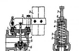
gas turbine engine - a device in which, as a result of fuel combustion, the temperature of the air (gas) entering it increases. Main K. s. turboprop engine or turbojet engine is located in front of the turbine and consists of a housing 6, forming a cavity for the flame tube (pipes) 5, inside which the fuel supplied by the injectors 2 is burned. The front (inlet) part of the flame pipe is the so-called front device 3, which ensures partial mixing of the fuel with air and hot gas, flame stabilization, combustion of part of the fuel. Through holes in the walls of the flame tube, the rest of the fuel is introduced into it to burn the remaining fuel, cool the combustion products and, together with the gas collector 7, form the required temperature field of gases entering the turbine. The temperature of combustion products depends on the excess air ratio. 1 slows down the air flow to a speed that allows efficient combustion of fuel with acceptable hydraulic losses in K.s. Igniter (or electric spark plug) 4 serves to initially ignite the fuel. To cool the flame tube, an air film is used at its inner wall, formed by air passing through small holes in the wall. Basic K. s. There are three types: tubular (one flame tube is located in a tubular-type housing), annular (one common flame tube of an annular shape is located in the annular space formed by the outer and inner housings), tubular-ring (flame tubes are located in a common annular space formed by the outer and internal housings). Until the 60-70s. Mainly tubular and tubular-ring capsules were used, then more compact ring capsules began to be used.
K. s. the second circuit of a turbojet bypass engine and K. s. A ramjet engine is similar in principle and design to an afterburner combustion chamber. The work of K. s. characterizes .
Aviation: Encyclopedia. - M.: Great Russian Encyclopedia. Editor-in-Chief G.P. Svishchev. 1994 .
See what a “combustion chamber” is in other dictionaries:
A closed space intended for burning fuel (gaseous, liquid, solid). There are periodic (for example, in piston internal combustion engines) and continuous action (in gas turbine and jet engines) ... Big Encyclopedic Dictionary
- – here the fuel burns and pushes the piston. EdwART. Dictionary of automotive jargon, 2009 ... Automobile dictionary
the combustion chamber- - [A.S. Goldberg. English-Russian energy dictionary. 2006] Energy industry topics in general EN burnerbnrfirebox ... Technical Translator's Guide
the combustion chamber- 3.1.26.1 combustion chamber: Chamber within which combustion of the gas-air mixture occurs. Source … Dictionary-reference book of terms of normative and technical documentation
Scheme of operation of a 4-stroke internal combustion engine Combustion chamber is a volume formed by a set of parts of an engine or furnace (in the latter case, the combustion chamber is called a firebox) in which the combustion of a combustible mixture or solid occurs ... ... Wikipedia
the combustion chamber Encyclopedia "Aviation"
the combustion chamber- Main combustion chamber. combustion chamber of a gas turbine engine is a device in which, as a result of fuel combustion, the temperature of the air (gas) entering it increases. Main K. s. turboprop engine or turbojet... ... Encyclopedia "Aviation"
A closed space intended for burning fuel (gaseous, liquid, solid). There are periodic (for example, in piston internal combustion engines) and continuous (in gas turbine and jet engines). * * * … encyclopedic Dictionary
the combustion chamber- degimo kamera statusas T sritis Energetika apibrėžtis Kamera dujoms ar degalams deginti. Degimas vyksta periodiškai (stūmokliniuose vidaus degimo varikliuose) arba nuolatos (dujų turbinose). atitikmenys: engl. combustion chamber vok. Brennraum, f... Aiškinamasis šiluminės ir branduolinės technikos terminų žodynas
A volume intended for combustion of gaseous, liquid or solid fuel. K. s. There are periodic actions for piston 2 and 4 stroke internal combustion engines (See Internal combustion engine) (ICE), and continuous ... ... Great Soviet Encyclopedia
Combustion chamber of a periodic engine
Engine combustion chamber- the volume formed by the totality of engine parts in which the combustion of the combustible mixture occurs. The design of the combustion chamber is determined by the operating conditions and purpose of the mechanism; As a rule, heat-resistant materials are used. Depending on the temperature developed in a continuous combustion chamber, the following are used as structural materials for their manufacture:
- up to 500 °C - chromium-nickel steels;
- up to 900 °C - chromium-nickel steels with titanium addition;
- above 950 °C - special materials.
The combustion chamber- this is a closed space, a cavity for burning gaseous or liquid fuel in internal combustion engines.
Combustion chamber of a gas turbine engine- a device in which, as a result of fuel combustion, the temperature of the air (gas) entering it increases.
Classification
According to the operating principle
- Continuous action(for gas turbine engines (GTE), turbojet engines (TRE), air-breathing jet engines (ARE), liquid rocket engines (LPRE)).
- Periodic action(for piston internal combustion engines (ICE));
Continuous combustion chambers, in turn, are classified as:
By purpose
- Basic;
- Reserve;
- Intermediate heating;
In the direction of air flow and combustion products
- straight-through;
- counterflow combustion chambers (the latter are rarely used due to high hydraulic resistance).
By layout
- Built-in;
- Remote;
According to the design features of the housing and flame tube
- Ring;
- Tubular-ring;
- Tubular;
Periodic combustion chambers, in turn, are classified as:
By fuel used
- Gasoline;
By design gasoline combustion chambers are divided into:
- Lateral
- Central
- Half-wedge
- Klinovaya
- Diesel.
By design diesel combustion chambers are divided into:
- Undivided (have only one compartment in which both mixture formation and fuel combustion occur)
- Divided (divided into two parts: main and additional, connected to each other by a neck. In this case, fuel is injected into the additional chamber)
According to the method of mixture formation
- Volumetric (for undivided combustion chambers);
- Film;
- Combined.
Continuous combustion chamber
Continuous combustion chambers are among the most important components of aviation and space propulsion systems, special and transport gas turbine units, which are widely used in the energy sector, chemical industry, and railways. transport, sea and river vessels.
Principle of operation
The combustion chamber is a component of a gas turbine engine (GTE) in which the air-fuel mixture is prepared and burned. To prepare the air-fuel mixture, fuel is supplied to the combustion chamber through injectors and air is supplied from the compressor. When starting the engine, the air-fuel mixture is ignited by an electric spark (or starting device), and during further operation the combustion process is maintained continuously due to the contact of the resulting air-fuel mixture with hot combustion products. The gas formed in the combustion chamber is directed to the compressor turbine.
The stability and perfection of processes in the combustion chamber largely ensure the reliable and economical operation of a gas turbine engine.
Requirements for a continuous combustion chamber
- Stability of the combustion process under all possible modes and flight conditions. It is necessary that the combustion of the fuel is continuous and there is no flameout or pulsating combustion, which can cause the engine to shut down. As the engine operating mode and flight conditions change, the ratio of fuel and air entering the combustion chamber changes, i.e. the quality of the mixture changes.
- Ensuring a uniform gas temperature field in front of the turbine. Combustion chambers typically have multiple injectors to supply fuel, so there is a tendency to have zones of varying temperatures as the gases exit the combustion chamber. Significant unevenness of the gas temperature field can lead to the destruction of turbine blades.
- Minimum flame length, i.e. The combustion process must end within the combustion chamber. Otherwise, the flame reaches the blades of the nozzle apparatus, which can lead to their burnout.
- Reliable operation, long service life, ease of control and maintenance. Ensuring long-term and reliable operation of the combustion chamber is achieved both by a number of design measures and by strict adherence to the rules of flight and technical operation. To ensure maximum fulfillment of the listed requirements, the appropriate type of combustion chamber is selected for each type of engine.
Batch combustion chamber
Combustion chamber running on gasoline

Gasoline engine with wedge combustion chamber

Hemispherical combustion chamber
The designs of combustion chambers of automobile engines are different. Engines with overhead valves use central chambers, as well as semi-wedge and wedge-type chambers. With the valves located at the bottom, the main volume of the combustion chamber is shifted away from the cylinder axis (L-shaped); This chamber design enhances the turbulence of the combustible mixture and improves mixture formation. On modern engines, semi-wedge and wedge-type combustion chambers are widely used.
Wedge combustion chamber- obtained from flat oval angled valves to obtain a better shape of gas channels. The spark plug in this case is shifted towards the exhaust valve, the movement of the charge in the chamber is directed towards the spark plug. In a wedge-shaped combustion chamber, most of its volume is concentrated near the spark plug, due to which the largest amount of charge should burn first, and in the zone of the combustion chamber farthest from the spark plug, where there is a danger of detonation, there should be a relatively small amount of supercooled mixture in the displacer gap. This chamber ensures soft combustion and low heat losses. The harshness of engine operation is assessed by the rate of increase in pressure, i.e., the increase in pressure in the cylinder when the crankshaft is turned is of decisive importance is the turning section corresponding to the interval between the formation of a spark discharge (ignition of the mixture) and TDC. The combustion process is considered soft when the rate of pressure increase is in the range of 0.2 - 0.6 MPa per 1° crankshaft rotation angle. The noise level during engine operation also depends on the clearances between the piston and cylinder and between the shaft and its bearings.
Widely used in the past semi-wedge combustion chamber is currently undergoing changes. A chamber of this shape is used in engines of sports and racing cars to achieve high power density. By using two camshafts in the cylinder head and a large valve angle, large diameter valves can be accommodated in the cylinder head. In this case, the surface of the combustion chamber in relation to its volume is quite small. Good flow of charge through the valves into the cylinder is also ensured, since it is not impeded by the walls of the cylinder or combustion chamber. The inlet and outlet channels are short in length and have a small surface area. Engines with such a combustion chamber have a fairly high efficiency.
Diesel combustion chamber
 A- Hemispherical undivided combustion chamber for volumetric mixture formation
b– toroidal undivided combustion chamber for volumetric mixture formation
G- Undivided combustion chambers for film mixture formation
d- undivided combustion chambers for combined mixture formation
In diesel engines, the requirements for the shape of the combustion chamber are determined by the mixture formation process. They take very little time to create a working mixture, since almost immediately after the start of fuel injection, combustion begins, and the remainder of the fuel is supplied to the burning environment. Each drop of fuel must come into contact with air as quickly as possible so that heat is released at the beginning of the expansion stroke.
Film mixture formation used in a number of combustion chamber designs, when almost all the fuel is directed to the near-wall zone. Approximately 5–10% of the fuel injected by the injector enters the central part of the combustion chamber. The rest of the fuel is distributed on the walls of the combustion chamber in the form of a thin film (10–15 microns). Initially, part of the fuel that gets into the central part of the combustion chamber is ignited, where there is usually no movement of the charge and the highest temperature is established. Subsequently, as it evaporates and mixes with air, combustion spreads to the main part of the fuel, directed into the near-wall layer. Film mixture formation requires a less fine atomization of the fuel. Nozzles with one nozzle hole are used. The fuel injection pressure does not exceed 17–20 MPa.
Film mixing compared to volumetric mixing provides better economic performance of the engine and simplifies the design of fuel equipment.
The main disadvantage is the low starting properties of the engine at low temperatures due to the small amount of fuel involved in the initial combustion. This disadvantage is eliminated by heating the air at the inlet or by increasing the amount of fuel involved in the formation of the initial source of combustion.
Combined mixing is obtained with smaller diameters of the combustion chamber, when part of the fuel reaches its wall and is concentrated in the near-wall layer. The other part of the fuel droplets is located in the internal volume of the charge. Approximately 50% of the fuel settles on the surface of the chamber. When entering the chamber, no rotational movement of the charge is created. The charge is set in motion when it is displaced from the space above the piston into the combustion chamber, and a vortex is created. The speed of the charge reaches 40–45 m/s.
A distinctive feature from film mixture formation is the counter-movement of jets of fuel and charge displaced from the space above the piston, which helps to increase the amount of fuel suspended in the volume of the combustion chamber and brings the process closer to volumetric mixture formation. Nozzles are used with sprayers having 3–5 nozzle holes
Combustion chambers with volumetric mixture formation. In diesel engines with such chambers, fuel is injected directly into the combustion chamber by a nozzle with a working pressure of 15–30 MPa, which has multi-hole nozzles (5–7 holes) with a small diameter of nozzle channels (0.15–0.32 mm). Such high injection pressures are used due to the fact that in this case, atomizing the fuel and mixing it with air is achieved mainly due to the kinetic energy imparted to the fuel during injection. To ensure uniform distribution of fuel in the chamber, the injectors of such engines are often made with several holes.
Requirements for all engine combustion chambers
The basic requirements for all continuous combustion chambers are:
- stability of the combustion process
- high thermal intensity
- maximum combustion efficiency
- minimal heat loss
- reliable operation during the specified engine operating life.
See also
Literature
- Ionin A.A. main and afterburner combustion chambers of a turbojet engine / Nenishev A.S., Lebedev V.M. - Omsk: Omsk State Technical University, 2005. - 92 p.
As is clear, combustion chambers must provide not only
not bad mixture formation, and even better performance
efficiency and starting properties of the motor. There are two constructive
groups of combustion chambers of diesel engines, separated from each other not only
design, and the principle of formation of the fuel mixture in the chamber. This
broken and undivided combustion chambers.
Broken combustion chambers
Such chambers have two interconnecting channels independent of the volume:
- prechamber;
- vortex chamber.
The vortex chamber can be placed either in the block head
cylinders and in the block itself. The cooling surface of the broken chambers is very
high. In this regard, the engine is prone to significant thermal losses,
which leads to a decrease in starting properties and a negative effect on the factor
efficiency. Typically, diesel engines with broken combustion chambers
provide a fairly high compression ratio.
The main advantage of broken combustion chambers is
production of virtually ideal fuel consistency. Thanks to the use
kinetic energy of gases due to flow between chamber cavities,
fuel combustion is greatly increased and exhaust smoke is minimized
systems.
In addition, the interaction of channels in broken cameras
assigns stability to the engine during its operation. The main
loads on such important parts as connecting rods, crankshaft, piston pins.
To somehow reduce the so-called roughness of diesel operation with
broken combustion chambers can also be due to an increase in temperature
mode of certain camera areas.
Undivided combustion chambers
Undivided combustion chambers, unlike broken ones, have
only volume and the simplest form, consistent with direction, number and
the size of the fuel flows of the injected fuel. Such cameras have very
small sizes, as follows, have a small cooling surface.
This is how thermal energy is lost in engines with undivided chambers
combustion is significantly less than in engines with broken chambers. Such
diesel has good starting and economic characteristics.
The shapes of undivided combustion chambers are distinguished by their
variety. More often they are designed in the piston heads. But it does occur
placement of chambers in the cylinder head, also partly in the piston heads
and partly in the head.
It is possible to break the undivided combustion chambers of diesel engines
engines according to their fundamental structural arrangement followed by
way:
- Toroidal in the piston.
- Hemispherical in the piston and head
cylinders - Hemispherical in the piston.
- Cylindrical in piston.
- Cylindrical in piston with side placement.
- Rounded in the piston.
- Balls in the piston.
- Toroidal with a neck in the piston.
- Cylindrical, formed with the piston bottom and
cylinder wall. - Vortex in the piston.
- Trapezoidal in the piston.
- Cylindrical in the cylinder head under
exhaust valve.
In combustion chambers of types 1, 2, 3,
4, 5 a very high degree of fuel consistency formation properties is obtained
thanks to fuel atomization and coordination of the forms of its fuel flows with
camera shapes. In such combustion chambers, nozzles are often installed,
having multi-hole nozzles that allow you to control the forms of fuel
flows, also use high injection pressure. These cameras
have very small cooling surfaces. For diesel engines with
the listed types of combustion chambers are characterized by low degree characteristics
compression.
For combustion chambers type 6, 7, 8,
9 features wider cooling surfaces. Although this is unconventional,
but it still affects the starting performance of the engine. But in the process
displacement of air above the piston into the combustion chamber at the moment of compression
vortex-type flows are created, which promotes good air mixing
with fuel, forming a fairly high-quality fuel mixture.
Combustion chambers type 10, 11, 12
used not only in diesel engines, but also in engines with
possibility of using different types of fuel. The corresponding feature of such cameras
is a serious direction of eddy currents that promotes evaporation
fuel and delivering it with a certain sequence to the required location
combustion. To improve performance in cylindrical chambers in the head
cylinder block under the exhaust valve use the highest exhaust temperatures
valve, which immediately forms the wall of the combustion chamber.
If the combustion chamber occupies the volume above the entire surface of the piston crown, then too large a cooling surface occurs. Therefore, they strive to create a compact combustion chamber in the area of the spark plug, and above the piston bottom - to form a gap between it and the surface of the cylinder head (the previously mentioned displacer area). This gap performs two functions - it ensures compactness and a small surface of the combustion chamber, and towards the end of the compression stroke it contributes to the creation of intense movement (turbulence) of the charge in it.
G. R. Ricardo identified the importance of charge turbulence already at the initial stage of development of internal combustion engines. The Ricardo combustion chamber, used in engines with side valves, significantly improved their parameters. Compact, located above the valves, it had a small surface area for heat transfer to the coolant, and the turbulence created by the propellant accelerated combustion. The swirling of hot gas near the walls of the combustion chamber, although it increases the heat transfer into them, but at the same time makes it possible to increase the degree of compression, which more than compensates for some increase in heat losses into the walls.
Currently, internal combustion engines are made with valves located in the cylinder head and camshafts located in the cylinder block (OHV design) or in its head (OHC design). The combustion chamber is formed above the piston bottom. To simplify the gas distribution mechanism, the valves are most often located on the longitudinal axis of the engine and the combustion chamber underneath them is usually made bath-shaped. To facilitate access to the spark plug, sometimes it is located on the side of the combustion chamber, and on the opposite side of the spark plug, a displacer is formed between the piston and the cylinder head. The charge displaced from it at the end of compression is directed towards the spark plug and enriches the mixture near it. Such bath-shaped (flat-oval) combustion chambers, with minor modifications, are used in almost all modern engines.
The so-called wedge combustion chamber, obtained from a flat oval by tilting the valves to obtain a better shape of the gas channels, is shown in Fig. 1. The spark plug in this case is shifted towards the exhaust valve, the movement of the charge in the chamber is directed towards the spark plug. In a wedge-shaped combustion chamber, most of its volume is concentrated near the spark plug, due to which the largest amount of charge should burn first, and in the zone of the combustion chamber farthest from the spark plug, where there is a danger of detonation, there should be a relatively small amount of supercooled mixture in the displacer gap. This chamber ensures soft combustion and low heat losses. The harshness of engine operation is assessed by the rate of pressure increase, i.e., by the increase in pressure in the cylinder when the crankshaft is turned by The turning section corresponding to the interval between the formation of a spark discharge (ignition of the mixture) and TDC is of decisive importance. The combustion process is considered soft when the rate of pressure increase is in the range of 0.2 - 0.6 MPa per 1° crankshaft rotation angle. The noise level during engine operation also depends on the clearances between the piston and cylinder and between the shaft and its bearings.
The previously widely used hemispherical combustion chamber is also currently undergoing changes. A chamber of this shape is used in engines of sports and racing cars to achieve high power density. By using two camshafts in the cylinder head and a large valve angle, large diameter valves can be accommodated in the cylinder head. In this case, the surface of the combustion chamber in relation to its volume is quite small. Good flow of charge through the valves into the cylinder is also ensured, since it is not impeded by the walls of the cylinder or combustion chamber. The inlet and outlet channels are short in length and have a small surface area. Engines with such a combustion chamber have a fairly high efficiency. In Fig. Figure 2 shows an example of a classic design of a hemispherical combustion chamber.
In modern racing cars this combustion chamber has been significantly modified. To reduce inertial forces in the valve mechanism, four valves are used in one cylinder, which leads to the formation of a combustion chamber of the so-called tent shape. It allows you to place one spark plug directly on the cylinder axis. To obtain high compression ratios in such chambers, the piston bottom has a convex shape, and recesses are made in it for the valves. In this regard, the piston becomes quite massive, which in the four-valve version caused the transition to a tent-shaped combustion chamber with a small angle of about 20° between the rows of valves. The use of such a combustion chamber ensures a large flow area of the valve seats, a low mass of parts of the gas distribution mechanism, suitable for high rotation speeds - up to 12,000 min -1, a small surface of the combustion chamber without large recesses for valves and a low piston mass. If the valve fails to close with this design, the piston will strike it but will not bend it and therefore will not cause serious damage to the expensive cylinder head.
For racing car engines, a fast combustion process is important, also ensured by strong charge turbulence. In this case, the axis of rotation of the charge should be parallel to the axis of the crankshaft, and the axis of the intake pipe should be as close as possible to the axis of the intake valve. In Fig. 3 shows a similar combustion chamber.
If a hemispherical combustion chamber in a two-valve design is used, then the valve axes should not intersect with the cylinder axis. Most often, the valves are slightly deviated from the cylinder axis, located in the spherical part of the chamber, and their recess into the piston in this case is small. Under the exhaust valve, a small recess is made in the bottom of the piston and the gap between the piston and the head provides the charge swirl necessary for smooth engine operation. The classic hemispherical combustion chamber is characterized by harsh engine operation.
Several new types of combustion chambers have been developed for burning highly lean mixtures. For the most part, they are characterized by the desire to achieve layer-by-layer charge distribution in the chamber volume with the formation of a rich mixture near the spark plug. Often these chambers have the shape of bodies of rotation and are located in the bottom of the piston. An example of such a camera is shown in Fig. 4. The tangential arrangement of the inlet channel relative to the cylinder ensures rotation of the charge around the cylinder axis, which increases even more at TDC after the charge is displaced from the periphery of the cylinder into a chamber whose diameter is less than the diameter of the cylinder. The spark plug is located in the chamber area where the mixture is rich. The cylinder head is flat, and the flow exit from the valve slot is not inhibited by either the cylinder wall or the wall of the combustion chamber. Immediately after opening the valve, its cross section is open for the passage of gas flow, with the exception of the area near the cylinder wall, but this is not of fundamental importance, since the rotation of the intake channel is not directed in this direction.
The piston with the combustion chamber located at the bottom has a large mass and its temperature is higher than the temperature of the wall of the combustion chamber located in the cylinder head. The latter causes a deterioration in heat transfer from gas to the cylinder head and a decrease in heat loss into the cooling system.
The size of the valve in the cylinder head is determined by the diameter of the cylinder. The valve disc should not protrude beyond the circumference of the cylinder, as this increases the cooling area and impairs cylinder cleaning. Large valve sizes are also impractical, since a significant part of its perimeter is obscured by the wall of the combustion chamber.
Increasing the intake valve diameter can be achieved by reducing the exhaust valve diameter, which can be 15% smaller than the intake valve. When the exhaust valve opens, the pressure in the cylinder is quite high, and good cleaning of the cylinder can be ensured even with a reduced valve cross-section. In addition, a smaller exhaust valve also has less seat deflection and cools faster.
The largest valve sizes can be obtained in a hemispherical combustion chamber, in which the diameter of the intake valve can reach 0.64, and the exhaust valve - 0.54 of the cylinder diameter. With a smaller camber of the valve axes, as well as the presence of valve seats in aluminum heads, the valve diameters are 10% less than the above values.