The constant availability of hot water in a house or apartment has long become a familiar norm for most people, without which it is difficult to imagine a normal, comfortable life. If a water supply is extended to the housing or an autonomous uninterrupted water supply is organized, for example, , then there is nothing to think about - you need to install a water heater of one type or another.

Probably the leading position in popularity among water heating devices for domestic needs are electric boilers. They are extremely easy to use, their installation does not require any additional conciliatory procedures or drawing up individual projects. Installation of such a boiler is quite feasible even for independent installation. That is why the information that will be presented in this publication is necessary - each of the home craftsmen must clearly understand how important a safety check valve is for
How would workers of housing and communal services, emergency and rescue services, state technical supervision authorities warned what would stories with the consequences of accidents have not been shown on television, still with alarming regularity there are “smart people” who benefit from all these technical recommendations and simply kind advice is not a decree, they themselves “know what is simpler and better.” Alas, ignoring a very small, inexpensive, easy-to-install, and at the same time extremely important object for piping an electric water heater can result in very big troubles, and, it is possible, even a tragedy.
First of all, it is necessary to immediately make a very important disclaimer. Although very often, in order to obtain information, those interested enter the search query “check valve for a water heater”; it would be much more accurate and correct to talk about a safety valve that combines several functions. These devices have a certain similarity, but there is also a huge difference, which predetermines the main task - security safe operation of an electric heater.
For comparison, consider the device of a conventional check valve:

This is how a regular check valve works. But it’s not enough for a boiler!
This is a metal cylinder, on both sides of which there are threaded sections for “packing” into a straight section of pipe of the appropriate diameter. A poppet valve is stopped inside - a disk with a rubber seal around the circumference, on the central axle - rod(shown in the figure with a green arrow). The disk is constantly in a spring-loaded state, blocking the internal channel for the passage of water.
When water is supplied in the direction of the arrow (the direction of the permissible liquid flow is always indicated on the valve body - this mark is shown with a red arrow in the figure), the pressure in the pipe through the “plate” compresses the spring and slightly opens the passage. As soon as the pressure decreases, the valve automatically returns to the closed state.
This precaution is, of course, necessary to ensure that the tank in the water heater is constantly filled, under any circumstances. However, such a measure is clearly not enough to ensure safety - this will be discussed below.
The safety valve is somewhat more complicated:

Essentially, these are two valves in one body, placed perpendicular to one another.
In the larger cylinder (item 1), which follows the flow of water, the same valve is installed, preventing the reverse flow of water. On the supply side there is a male threaded section (item 2) for insertion into the water supply system (in particular, it will be convenient to connect a flexible water supply hose here). On the opposite side there is a female threaded coupling (item 3), which in some cases is screwed directly onto the standard cold water supply pipe in the electric heater.
The figure clearly shows the check valve “plate” (item 4) with a sealing ring around the circumference, and the spring (item 5) that holds the valve closed.
Now here is the main difference. Perpendicular to the cylinder with a check valve there is another one, somewhat smaller in size (item 7). In fact, it contains the same poppet valve, but its spring is much more powerful - this is the same safety “breakdown” valve. Normal and even slightly increased pressure in the water supply system will not be able to compress the spring and open it - this requires much more serious efforts.
In the cylinder cavity behind the safety valve “plate” there is necessarily a hole with a pipe (pos. 8), where excess liquid will be discharged when the valve is activated.
A cylinder with a safety “breakdown” valve can be completely plugged, and sometimes it ends with a threaded plug (plug), behind which there is an adjusting screw (usually with an “internal” hexagon). But the most common safety valves are those with an additional lever:

The figure clearly shows the features of such a device. The lever (pos. 9) is intended for manual opening of the safety valve with water discharge through the pipe (pos. 8). Please note that the pipe may have a special relief design, which allows you to put thin hoses on it to drain water into the drainage (sewer). The manual valve control function can be convenient, for example, for draining the contents of a boiler during repair or maintenance work. However, you should not get carried away with using such manual control - this can in some cases even be dangerous (this will be discussed below).
Any safety valve always has an arrow indicating the direction of cold water flow towards the water heater. (there is a red arrow in the diagram). Very often, the maximum operating pressure of the “stall” valve is indicated on the body - in this case it is 0.7 MPa or 7 atmospheres (yellow circle in the figure).
How does a safety valve work in different situations?
To fully understand the importance of a safety valve, it is best to consider the cases in which it operates, as well as the situations that may arise if for some reason the valve is missing or faulty.
For clarity, once again - the simplest, but also the most understandable scheme for piping a boiler with a safety valve. The blue and red arrows show the direction of flow of cold and hot water, respectively. The green arrow points to the installation location of the safety valve.

1. After the electric one is installed and completely “tied”, it should be filled. To do this, simply open the cold water supply and the hot tap on one of the mixers. There is enough pressure in the water pipe to open the check valve to allow unimpeded flow. As the volume of the water heater tank fills, air is displaced. As soon as water flows from the mixer, the entire container is filled to the upper intake pipe, the supply can be turned off.
The pressure in the boiler at this moment is approximately equal to the pressure in the cold water main - it is, as it were, “propped up” by it. However, it may even be a little higher - due to the remaining compressed small volume of air in the upper part of the tank. Plus, when the power is turned on, the water begins to heat up - and this, of course, also leads to an increase in pressure.
2. Let's imagine a situation where the check valve is not installed or is in a faulty condition. The equilibrium that was achieved when filling the boiler tank is sooner or later disturbed, since the pressure becomes higher than the pressure in the pipe. The “hot” taps on the mixers are closed, which means that the heated water will look for an outlet in a different direction. This can lead to hot water suddenly starting to flow from a “cold” tap, or to filling the toilet flush tank with it. Meanwhile, the boiler thermostat cannot understand the situation and does not give a signal to turn off the heating elements. Expensive electrical energy is completely wasted.
3. But this is not the saddest thing. It is no secret that the pressure in the water main, especially in multi-storey buildings, often drops to critical values (from the tap, as they say, it barely flows), or even disappears completely. There are a great many reasons for this, for example, an accident on the highway, maintenance work, a planned reduction in pressure, for example, at night, etc. What happens if the check valve is missing or faulty? Nothing good - the boiler will simply empty, since all the water from it will completely flow into the supply pipes.
It’s good if the boiler has protection against “dry” heating, and it will work quickly! And if not? Powerful heating elements will idle heat the air in a closed volume, and this will end either in their burnout or cracking of the enamel - in any case, nothing good can be expected in such a situation.
4. A reasonable question may arise - is it possible? limit myself only by installing this same check valve? It would seem, judging by the description, that he is able to solve all problems.

Do not consider it an exaggeration: such an installation is like a bomb planted in your home!
No, under no circumstances is it possible. The installation of a complex valve that combines both non-return and safety valves is a prerequisite for the safe operation of the water heater.
If somewhere the reader comes across a similar picture - only a check valve at the inlet, then he should understand that this is comparable to a planted powerful bomb, which will explode unknown when.

Another example of “suicidal creativity”
Let's look at the situation in detail. When the boiler is turned on, heating begins, and as the temperature rises, according to the laws of thermodynamics, the pressure in a closed volume begins to increase.
Designers of household appliances include a certain operational resource in each water heater, allowing the device to operate up to certain pressure values in the tank - usually this value is indicated in the technical documentation. Typically, all boilers are very balanced thermodynamic systems, in which the optimal ratios of permissible temperatures and pressure levels are very accurately calculated. Nevertheless, anything can happen. And as soon as the pressure level, for some reason, begins to approach the permissible upper mark, the spring on the safety valve is compressed, and the resulting excess liquid is discharged into the drain pipe. As a result, the system again enters a state of dynamic equilibrium.

Water coming out of the drain pipe is normal.
Now let’s try to imagine what can happen in a situation where there is no emergency valve, and everything is limited only by the return
Water heating should be limited by a thermostatic regulator, but quite often these electromechanical devices are far from perfect and can simply fail. In this case, heating continues uncontrollably.
The pressure inside the boiler tank is growing, but there is no way out - the mixers are closed, and the check valve has reliably shut off the supply line. It would seem that the temperature will only reach 100 degrees, to the boiling point of water? Nothing like this! As the pressure in a closed volume increases, the boiling point of the liquid also increases sharply. For example, the data is shown in the table:
| Pressure in a closed volume, atm (MPa) | Water boiling point, °Ċ |
|---|---|
| 1.0 (0.1) | 99.09 |
| 1.033 (0.1) | 100.0 |
| 1.5 (0.15) | 110.79 |
| 2.0 (0.2) | 119.62 |
| 2.5 (0.25) | 126.79 |
| 3.0 (3.0) | 132.88 |
| 4.0 (0.4) | 142.92 |
| 5.0 (0.5) | 151.11 |
| 6.0 (0.6) | 158.08 |
| 7.0 (0.7) | 164.17 |
| 8.0 (0.8) | 169.61 |
| 9.0 (0.9) | 174.53 |
| 10.0 (1.0) | 179.04 |
| 20.0 (2.0) | 211.38 |
| 25.0 (2.5) | 222.90 |
| 50.0 (5.0) | 262.70 |
| 100.0 (10.0) | 309.53 |
When the word “bomb” was mentioned above, this is not at all an exaggeration! In such circumstances, the water heater becomes really a scary explosive device destructive force.
Already at 4 - 5 atmospheres of pressure the boiling point reaches almost 150 ° WITH, and continues to rise. An increase in pressure on the walls can lead to their deformation, chipping of the enamel or ceramic coating - but this will be the least of all possible evils. Another scary circumstance is a sharp drop in pressure in this closed system, and this can happen when a crack appears in a weld, when a rubber seal breaks, or even simply when a hot water tap is opened.
A sharp decrease in pressure leads to a corresponding sharp decline boiling temperature of water. As a result, the entire volume of liquid (imagine all 50, 80 or 100 liters at the same time!) instantly boils, which, of course, is accompanied by the release of a colossal amount of steam. No one, even the most durable building, can withstand this - a powerful explosion follows, which is capable of demolishing everything in its path, including even brick interior walls. There are many clear examples of this on the Internet.

It's hard to believe, but these are the consequences of an explosion of an ordinary electric boiler
So, let's briefly summarize the issue of the need for a safety valve.
— It prevents reverse leakage of water from the tank into the supply pipeline in the event of a decrease in pressure.
The presence of a valve at the inlet creates additional protection for the boiler from possible strong pressure surges in the water supply and from water hammer.
— The safety valve will eliminate possible shortcomings in other safety levels - it will maintain the temperature-pressure regime in the boiler within acceptable values.
— A safety valve equipped with a lever also allows water to be drained from the boiler if necessary.
Video: Is it necessary to install a safety valve on the boiler?
Recommendations for selecting and installing a safety valve
Selecting the right valve is not difficult. Most often, boilers (especially from leading manufacturers) go on sale complete with a valve of the required rating. You will need to focus on the same value if for some reason you have to change the valve in the future.
The maximum pressure value in the boiler tank must also be indicated in the technical documentation of the product. If the water heater is not equipped with a valve, you will have to purchase it yourself, based on the value indicated in the passport. It is important to choose the right rating here - if you install a valve that is too “weak”, water will leak from it almost continuously. A valve with too strong a spring will not create absolutely safe operating conditions.
The valve can be “packed” directly onto the boiler pipe for cold water (always has a corresponding blue color marking. For reliable sealing during installation, it is best to use flax tow with modern sealing pastes. When tightening, 3–4 full turns are usually sufficient. If there is a flexible liner underneath , then a rubber sealing gasket is sufficient.

Sometimes a drain valve is inserted between the valve and the boiler itself - this greatly facilitates periodic maintenance work. Such an installation is quite acceptable, but only under one condition - the valve must be located at the outlet of the tee, but in no case should it interrupt the direct channel from the water heater to the valve. Any shut-off valves on this straight section are strictly prohibited!
Step-by-step instructions for wiring an electric water heater
It makes sense to consider step by step how you can independently connect an electric boiler to the water supply system. The table below shows two options as examples. Despite some differences, in both cases it will still be clearly demonstrated that the safety valve is a mandatory element of the piping of such a water heater.
| Illustration | Brief description of the operation performed |
|---|---|
 | To begin with, a few words about installing the water heater itself on the wall. Of course, the location is thought out in advance, before purchasing the device, so that the boiler fits in the space allocated to it and does not interfere with the normal operation of the room. A power cable connected to a separate machine is usually installed in advance at the installation site. Insertion points into the water supply system are also immediately provided. To accurately hang the boiler on the wall, its height is measured. |
 | Knowing the height of the water heater, it is easy to determine the lowest point of the position of the device that it will occupy after installation. |
 | On the back side of the water heater body there are devices for mounting on the wall. In this case, it is a regular mounting strip (bracket) that will cling to the hooks. There may be other options - the device’s instruction manual usually describes all this, and often 1:1 templates are also included to simplify the marking process. |
 | In this case, it is necessary to determine the location of the line on the wall along which the hooks will be mounted. To do this, measure the distance from the lower end of the water heater to the mounting plate. |
 | The same distance is marked on the wall vertically from the previously designated point of the planned lower edge of the boiler. |
 | With control over the building level, a horizontal line is drawn along which the hooks will be located. |
 | The next step is to measure the required distance between the hooks. In this case, 200 mm will be optimal - the hooks will be placed closer to the edges of the mounting strip, but there will still be the possibility of a slight play left and right to align the water heater. |
 | This distance is transferred to the intended horizontal line - the centers of the holes for the hooks are marked. In the example shown, they landed rather poorly - exactly on the seams between the ceramic tiles. If there is such a possibility, then it is better to mark the holes away from the edge of the tile - the likelihood of a crack appearing when drilling holes is much less. |
 | Powerful hooks were chosen to hang the boiler: the outer diameter of the polymer dowel plug is 14 mm, the length of the dowel is 80 mm, the diameter of the metal hook is 8 mm. Often, the electric water heater kit already includes the fasteners recommended for installation. |
 | At the designated points, the corresponding holes are drilled with a hammer drill, into which dowel plugs are driven. Then the hooks themselves are screwed in. |
 | The hooks are screwed in to such a depth that a reliable, stable fit of the water heater is ensured, without play, but also without jamming. |
 | That's it, the boiler is hung on the wall. From below you can clearly see two pipes through which the device will be connected to the home water supply system. The pipes are color coded: blue – cold water supply, red – hot water outlet. |
 | The appropriate connection has already been made into the water supply system - here are two polypropylene pipes to which the water heater pipes need to be connected. On the left is the hot water supply pipe, on the right is the cold water supply pipe. |
 | In the example under consideration, the master decided to equip the entrance to the boiler with an optional element - an additional tap, which will be used if it is necessary to empty the boiler. To do this, a tee will be installed on the inlet pipe of the water heater. The recommended preliminary “fitting” is carried out - how many revolutions are needed for the swarm outlet to take the required position. In general, it is advisable to carry out such fittings before assembling any fixed assembly - there is less chance of making a mistake. |
 | After this, the tee is packed onto a tow winding coated with Unipak sealing paste. |
 | The tee is packed and given its intended position. |
 | A compact tap will be mounted on the side branch pipe of the tee. |
 | The tow is wound up and sealing paste is applied. |
 | The tap is screwed in, tightened with a key, at least three turns, and given the planned position for easy access to the handle. |
 | But now it’s time to install a mandatory element - a safety valve. Be sure to pay attention to the arrow showing the direction of water flow. |
 | The safety valve will be installed on the lower pipe of the already installed tee. The basic rule is fully observed - there are no locking devices between the valve and the water heater. The valve installed on the side branch of the tee does not have any effect on the safety of operation of the device. |
 | The valve is packed onto a tee - in the illustration this entire assembly is assembled. |
 | It is advisable to make the boiler piping dismountable - this will make it possible to turn off the device to remove it, for example, for maintenance or to replace the heating element or anode rod. Therefore, the foreman decided to install shut-off ball valves with an “American” union nut at both inputs. An example of such a tap is shown in the illustration. |
 | The tap itself will be tightly packed onto the lower branch pipe of the safety valve. And a fitting for transition to a polypropylene pipe will be mounted on the fitting with the union nut itself. That is, it will not be difficult to disconnect the boiler from the pipes. |
 | A second similar tap is installed for hot water, but directly on the outlet pipe of the water heater. And it is also assumed that a fitting for transition to a polypropylene pipe will be packaged with the removable fitting with the “American” one. |
 | Here the fitting mounted to the tap fitting is tried on at the installation site. In this case, a 90-degree elbow fitting was used to immediately lead the pipe closer to the wall. |
 | Next, another bend will be welded in - and the pipe will go down along the wall. |
 | A regular fitting for switching to polypropylene is mounted on the fitting of the second tap for hot water. But this was done solely for reasons of aesthetics in the appearance of the piping - so that the “step” of transition to a level closer to the wall on both pipes is located at the same height. Next, the usual welding and installation work with polypropylene pipes is carried out. |
 | This is how neat the overall water heater piping unit turned out to be. |
 | And this illustration shows how the supply pipes are welded into the previously left water supply pipes. The water heater installation is complete. You can open all the taps (except the drain), fill the boiler with water, and connect to the power supply. If necessary and possible, a transparent PVC pipe is placed on the drainage pipe of the safety valve, which is discharged into the sewer, toilet flush tank or some container - the excess water released will not fall on the floor. |
 | Now let's consider a possible option for piping the boiler with the installation of a flexible line. The illustration shows that the water heater is already hung on the wall. The arrow shows one of the “water outlets” - pipes hidden in the wall under the finishing of cold and hot water pipes. |
 | Conventional ball stop valves will be packaged onto these connections. In this case, there is no particular need to use taps with a union nut - the piping will be dismountable due to the use of a flexible connection. |
 | The nozzle is wound with flax tow. Some craftsmen use FUM tape, but there are still many more supporters of reliable sealing using tow. |
 | The winding is coated on top with Unipak sealing paste. |
 | Then the tap itself is screwed on - first it is baited by hand... |
 | ...and after that, it is tightened with a wrench, so that the “lamb” is located in a place convenient for use – at the top. |
 | A similar operation is completely repeated with the second tap. That's it for now. |
 | Let's move on to operations directly on the boiler itself. Its two pipes are ready for further installation. |
 | A sealing winding is performed at the inlet pipe - a safety valve will be installed here. |
 | In this case, the master decided to limit himself to only the valve, that is, to do without installing a drain valve on the tee. A completely normal solution - you can drain the water from the boiler through the valve - a special lever is provided for this. Draining will take a little longer, but installation is simpler and cheaper, and you still don’t have to resort to emptying the boiler very often. |
 | The valve is screwed on and then tightened with a wrench so that the lever and drain pipe are in a position convenient for the user. In fact, this was the last connecting node, requiring winding of tow. |
 | The safety valve is installed in its original place. |
 | Flexible hoses are connected. In this case, the master used high-quality corrugated stainless steel hoses, which, according to their characteristics, are considered “eternal.” A flexible hose made of a rubber or plastic hose in a metal braid is, of course, significantly inferior in reliability, and is attractive only due to its low price. The installation principle is completely identical. Hoses in length are purchased taking into account the distance from the boiler to the “water outlets”. The gasket that comes with it is inserted into the union nut of the hose, then the nut is inserted onto the thread of the pipe (in this case, the outlet). No winding is necessary if the end of the pipe along the entire circumference is in normal condition - the gasket will provide the required level of sealing of the connection. The union nut is first screwed on by hand until it stops... |
 | ...and then tightened literally another ¼ ÷ ½ turn with a wrench. There is no point in over-tightening the connection - you can pinch the gasket and thereby achieve just the opposite result. |
 | The second end of the flexible hose is connected in the same order to the threaded pipe of the faucet on the corresponding “water outlet”. |
 | The installation of the second hose is carried out in a similar way, with the only difference being that its upper end is connected to the safety valve branch pipe. Now you can turn on the water and check all connections for leaks. If a “tear” is detected, you can slightly tighten the connection with a wrench, without applying much force - the leak should disappear. |
 | If there are no leaks, you can proceed to full operation of the water heater. The illustration shows the “lower node” of the boiler piping: a flexible line is connected to the taps of the “water outlets”. |
 | And these are the same hoses, but connected from above to the safety valve (for cold water) and to the hot water outlet pipe. The boiler installation is complete. |
Video - Check valve on water heater
Frequently Asked Questions (F.A.Q.)
And finally, it makes sense to answer some of the most frequently asked questions regarding the operation of boilers with a safety valve.
- People often ask how to deal with annoying drops of water protruding from the drain pipe?
But there is no need to fight them - they only indicate that the valve is functioning normally. The easiest way is to put a transparent tube on the pipe (so that you can visually control it) and lead it either into a sewer pipe or, for example, into a toilet flush cistern.
- Is it possible to place the valve so that it is not visible?
By and large, if he is so annoying, then it’s okay. But at the same time, certain conditions must be met:
— No additional elements are allowed between the valve and the boiler - shut-off valves, tees, etc.
— The length of the section from the valve to the entrance to the boiler should not exceed one and a half to two meters. The fact is that the vertical column of water in the pipe will put additional pressure on the safety valve spring, and it will begin to work incorrectly, with severe undercutting.
- Leakage from the valve is too frequent and abundant, even at low water heating temperatures. What can be done?
The reasons for this phenomenon may be different.
— The valve rating does not correspond to the characteristics of the water heater.
— the spring in the valve simply weakened over time.
In both cases, the valve should be replaced with a new one with the required actuation force.
Another reason may lie in the instability of pressure in the water supply system. For example, frequent pressure surges with a large amplitude lead to valve activation even in the absence of heating. In this case, it is recommended to install a pressure reducer at the entrance of the water supply to the house (apartment).
- Can I try to adjust the valve myself using adjusting screws?
Definitely no! Adjustment of such devices requires " calibrated» pressure, and carrying out such procedures on your own is prohibited. The valve is not such an expensive product that it is impossible to purchase a new one of the required rating.
- I never saw even a drop of water come out of the valve. This is fine?
And here this is a very worrying sign. Who knows, perhaps the valve is simply “calming” with its appearance, but is completely inoperative. For example, the chamber behind the disc spring is overgrown or clogged with scale, the pipe is clogged, etc. If the valve is equipped with a lever, then you can try to check it manually (only better - at low heating temperatures, about 40 degrees, so as not to get burned).
It is possible that the valve rating is too high - it does not correspond to the water heater model. In addition, manufacturing defects cannot be completely ruled out.
The best way out of this situation remains the same - replacing the safety valve with a new one.
It will be calmer this way!
Never skimp on your own safety!
Video - Tricks for connecting an indirect heating boiler
Union of Soviets
Socialist
Republics
State Committee
“on matters of invention and discovery (53) UDC 621.646 (088.8) O 2) Authors of the invention
V. P. Zhukov and B. I. Shcherbinkin
4 (71) Applicant (54) SHUTOFF AND DRAIN VALVE
The invention relates to valve engineering and can be used in hydraulic and pneumatic systems to shut off and relieve pressure in gas and hydraulic communications.
Shut-off and drainage valves are known, including a body, inlet and outlet pipes, main and drainage seats, and an axially movable shut-off element. with main and drain sealing surfaces and lead screw with fork $1).
A disadvantage of the known shut-off and drainage valves is the presence of leaks of the working medium between the inlet and drainage pipes at the moment the valve is activated.
The purpose of the invention is to prevent leakage of the working medium between the inlet and drainage pipes.
This goal is achieved by the fact that the shut-off body consists of two valves spring-loaded relative to each other, the main one and the drainage one, while the drainage valve is made in the form, enclosing the rod, of the main valve of the sleeve with the shank and is connected to the fork in such a way that the end of the shank contacts only with the external supporting surface of the fork, and the main bolt rod - only with the internal one.
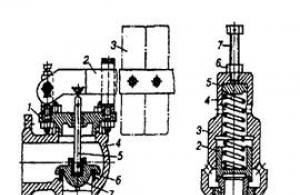
The drawing schematically shows the proposed device.
The shut-off and drain valve consists of a housing 1 with inlet 2, outlet 3 and drain 4 pipes. The body contains a main seat 5 and a drain seat 6, which are covered by a shut-off valve 7, consisting of a main valve 8 with a rod 9 and
15 of the drainage valve, made in the form of a bushing 10 covering the rod 9 with a shank 11. Between the end of the shank 11 and the rod 9, the eye of the fork 12 of the running screw 20 and 13 is inserted. Between the gate 8 and the bushing
10 spring 14 is installed.
The shut-off and drain valve works as follows.
In the initial position the working fluid
25 is located in the inlet line, the main valve 8 is pressed against the seat 5 by the force transmitted by the supporting surface 15 of the lead screw 13 through the shank 11 of the drain valve 10.
30.When unscrewing screw 13 from the housing
1 the supporting surface moves
15 of the screw and allows the drainage valve 10 to move under the action of the spring 14, which continues to press the main valve 8 against the seat 5 with a force sufficient to seal the seal of the container “main valve-seat”. With further unscrewing of the screw 13, the drainage valve 10 is pressed against the seat 6 by the force of the spring 14, which is also sufficient to seal the seal
"drainage valve-saddle". The drainage line is blocked. Moving further, the lead screw 13 with the supporting surface 16 presses the main valve 8 from the seat 5, brings the main valve all the way to the drainage valve
10 and presses the latter to the saddle 6.
The input line is connected to the output line. Drainage of the working fluid in the output line is carried out by screwing screw 13 into housing 1, and the input line is closed first and only after that the drain valve 10 moves away from the seat 6. Thus, when the valve is activated, one of the valves (main or drain) is located in contact and is pressed against its seat with the force necessary for sealing, and completely eliminates the possibility of simultaneous communication of the inlet, outlet and drainage lines.
Claim
Shut-off and drain valve, including a body with inlet, outlet and drainage pipes, main and drainage seats, an axially movable shut-off body with main and drainage sealing surfaces and a lead screw with a fork, characterized in that, in order to eliminate leaks of the working medium between the inlet and drainage pipes, the shut-off element consists of two spring-loaded valves, the main one and the drainage one, while the drainage valve is made in the form of a main valve sleeve with a shank, enclosing the rod, and is connected to the fork in such a way that the end of the shank has contact with the outer supporting surface of the grip, and the main shutter rod with the inner one.
Sources of information taken into account during the examination
A mandatory element of equipping autonomous water supply systems in dachas and country houses is a check valve. It is such a technical device, which can have different designs, that ensures the movement of liquid through the pipeline in the required direction. Check valves installed in an autonomous water supply system reliably protect it from the consequences of emergency situations. Referring to direct-acting valves, check valves operate automatically using the energy of the working medium transported through the pipeline system.
Purpose and principle of operation
The main function that a water check valve performs is that it protects the water supply system from critical flow parameters of the liquid transported through the pipeline. The most common cause of critical situations is stopping the pumping unit, which can lead to a number of negative phenomena - draining water from the pipeline back into the well, spinning the pump impeller in the opposite direction and, accordingly, breakdown.
The installation of a check valve on the water allows you to protect the water supply system from the listed negative phenomena. In addition, the water check valve prevents the consequences caused by water hammer. The use of check valves in pipeline systems makes their operation more efficient, as well as ensures the correct functioning of the pumping equipment with which such systems are equipped.

The principle of operation of the check valve is quite simple and is as follows.
- The flow of water entering such a device under a certain pressure acts on the locking element and presses the spring, with the help of which this element is kept closed.
- After the spring is compressed and the shut-off element is opened, water begins to move freely through the check valve in the required direction.
- If the pressure level of the working fluid flow in the pipeline drops or the water begins to move in the wrong direction, the spring mechanism of the valve returns the shut-off element to the closed state.
By acting in this way, the check valve prevents the formation of unwanted backflow in the piping system.

When choosing a valve model installed on a water supply system, it is important to know the regulatory requirements that manufacturers of pumping equipment impose on such devices. The technical parameters by which a check valve for water is selected in accordance with these requirements are:
- working, test and nominal closing pressure;
- diameter of the landing part;
- conditional capacity;
- tightness class.
Information on what technical requirements a water check valve must meet is usually contained in the documentation for the pumping equipment.

To equip domestic water supply systems, spring-type check valves are used; the nominal diameter is in the range of 15–50 mm. Despite their compact size, such devices demonstrate high throughput, ensure reliable operation of the pipeline, low noise and vibration levels in the pipeline system on which they are installed.
Another positive factor of using check valves in a water supply system is that they help reduce the pressure created by the water pump by 0.25–0.5 Atm. In this regard, a check valve for water allows you to reduce the load both on individual elements of pipeline equipment and on the entire water supply system as a whole.
Design features
One of the most common materials used to make the body of water return valves is brass. The choice of this material is not accidental: this alloy demonstrates exceptionally high resistance to chemically aggressive substances that may be present in water transported through a pipeline in a dissolved or suspended state. Such substances, in particular, include mineral salts, sulfur, oxygen, manganese, iron compounds, etc. The outer surface of the valves, which during their operation is also exposed to negative factors, is often protected with a special coating applied by the galvanic method.
The check valve device requires the presence of a spool, for the manufacture of which brass or durable plastic can also be used. The sealing gasket present in the check valve design can be rubber or silicone. To manufacture an important element of the locking mechanism - the spring - stainless steel is usually used.

So, if we talk about the structural elements of a spring check valve, then this device consists of:
- composite type housings, the elements of which are connected to each other by means of threads;
- a locking mechanism, the design of which includes two movable spool plates mounted on a special rod and a sealing gasket;
- a spring installed between the spool plates and the seat at the outlet of the through hole.
The principle of operation of a spring check valve is also quite simple.
- The flow of water entering the check valve under the required pressure acts on the spool and depresses the spring.
- When the spring is compressed, the spool moves along the rod, opening the passage hole and allowing the fluid flow to move freely through the device.
- When the pressure of the water flow in the pipeline on which the check valve is installed drops, or in cases when such a flow begins to move in the wrong direction, the spring returns the spool to its seat, closing the throughput hole of the device.

Thus, the operation scheme of the check valve is quite simple, but nevertheless ensures high reliability of such devices and the efficiency of their use in pipeline systems.
Main types
Having understood how a check valve installed in a water supply system works, you should also understand how to choose it correctly. The modern market offers various types of check valve devices, the design, material of manufacture and operation scheme of which can vary significantly.
Sleeve type spring check valveThe body of this type of valve consists of two cylindrical elements connected to each other using threads. The locking mechanism includes a plastic rod, upper and lower spool plates. The position of the elements of the locking mechanism in the closed state, as well as their opening at the moment when the pressure of the water flow reaches the required level, is ensured by a spring. The component elements of the housing are connected to each other using a sealing gasket.

The distinctive features of this type of shutter are easy to see even in the photo. The brass body of such a valve in its middle part, where the spool chamber is located, has a spherical shape. This design feature allows you to increase the volume of the spool chamber and, accordingly, the throughput of the check valve. The locking mechanism of this type of water valve, which is based on a brass spool, works on the same principle as in any other type of valve device.

Many of those who decide to independently install a pipeline system often have a question about why they need a check valve equipped with drainage and air vent systems. The use of check valves of this type (especially for equipping pipelines through which hot working fluids are transported) makes it possible to simplify the process of installation and maintenance of such systems, increase their reliability, reduce the total hydraulic pressure, and reduce the number of installation connections.
On the body of this type of valve, which can be seen even in the photo, there are two pipes, one of which is used for installing an air vent, and the second serves as a drainage element. The branch pipe for the air vent, on the inner surface of which is threaded, is located on the device body above the spool chamber (its receiving part). Such a pipe is needed to bleed air from the pipeline system, for which a Mayevsky valve is additionally used. The purpose of the pipe, which is located on the opposite side of the body - at the outlet of the valve, is to drain the liquid accumulated after the valve device from the system.

If you install a horizontal check valve, its air outlet pipe can be used to mount a pressure gauge. If you place the combined check valve vertically on the pipeline, then its drainage pipe can be used to drain water accumulated after such a device, and the air vent pipe can be used to remove air pockets from the part of the pipeline that is located before the check valve. That is why, when deciding how to install a combined type check valve, you should clearly understand what functions such a valve should perform.
Spring valves with polypropylene bodyCheck valves, the body of which is made of polypropylene, even if you look at the photos of such devices, look very similar to oblique bends. These types of check valves, for installation of which the polyfusion welding method is used, are installed on pipelines also made of polypropylene. An additional oblique outlet in the design of gates of this type is necessary to accommodate the elements of the locking mechanism, which facilitates the maintenance of such a device. Thanks to this design solution, it is not difficult to carry out maintenance and repair of a check valve of this type - it is enough to remove the elements of the locking mechanism from its additional outlet without violating the integrity of the device body and the tightness of its installation in the pipeline system.

In pipeline systems designed to transport water, other types of check valves can be installed.
- The check valve is equipped with a special shut-off element - a spring-loaded petal. The big disadvantage of valves of this type is that when they operate, significant shock loads are created. This negatively affects the technical condition of the valve itself, and can also cause water hammer to occur in the pipeline system.
- Double-leaf check valve devices are compact in size and light in weight.
- The lift coupling check valve includes a spool as a shut-off element that moves freely along the vertical axis. The operation of the locking mechanism can be based on the gravitational principle, when the spool returns to the closed state under the influence of its own weight. A spring can also be used for this purpose. If you decide to install a gravity check valve on the pipeline, keep in mind that such a device can only be installed on vertical sections of the system. Meanwhile, the gravity valve is characterized by a simple design, while demonstrating high reliability during operation.
- There are check valves whose closing element is a spring-loaded metal ball. The surface of such a ball can be additionally covered with a layer of rubber.

When deciding which check valve is better and whether an expensive valve of a more complex design is needed in the pipeline system, you should first get acquainted with the technical characteristics of such a device and compare them with the operating parameters of the pipeline system. The main purpose of a check valve, as mentioned above, is to pass water through the pipeline in the desired direction and prevent the flow of liquid from moving in the opposite direction. In this regard, you should choose a check valve for water based on the pressure under which the water flow moves in the pipeline. Naturally, it is necessary to take into account the diameter of the pipes on which such a valve should be installed.
When installing a pipeline, you should also keep in mind that you can install a check valve in various ways. On large-diameter pipes, flange and wafer-type check valves are installed, and on small-diameter pipes, coupling valve devices are installed. The welded method of installing check valves is used mainly for installation on polypropylene and metal-plastic pipes.
If you choose the right check valve and the method of its installation, such a device will not only last for a long time, but will also ensure the correct operation of the entire pipeline system.
How to install correctly
Having understood the question of why a check valve is needed and its role in the pipeline system, you should also study the rules for installing it on an already operating or newly created pipeline. Such devices are mounted on various elements of pipeline systems:
- on pipelines of autonomous and centralized water supply;
- on suction lines served by deep and surface pumps;
- in front of boilers, cylinders and water flow meters.

If you are interested in check valves that can be installed in both vertical and horizontal positions, choose spring models rather than gravity ones. You can find out in which direction the water flow should move through the valve by looking at the special arrow marked on the body of the device. When installing coupling-type check valves, be sure to use FUM tape for good sealing. In addition, we should not forget that check valves require regular maintenance, so they must be installed in accessible places in the pipeline.
When installing a check valve on the suction line of a submersible pump, care should be taken to install a coarse filter in front of such a device, which will prevent mechanical impurities contained in underground water from entering the inside of the device. A perforated or mesh cage can also be used as such a filter, into which a check valve installed at the inlet end of the suction line of a submersible pump is placed.
When installing a check valve on an already operating pipeline, you must first disconnect the system from the water supply and only then install the shutter device.
How to make your own check valve
The simple design of the check valve allows you to make it yourself if necessary.

To solve this task you will need the following materials and tools:
- tee with internal thread, which will serve as a housing;
- a coupling with a thread on the outer surface - the seat of a homemade check valve;
- rigid spring made of steel wire;
- a steel ball, the diameter of which should be slightly smaller than the diameter of the hole in the tee;
- a steel threaded plug that will serve as a stop for the spring;
- a standard set of plumbing tools and FUM sealing tape. (votes: 1 , average rating: 5,00 out of 5)
The content of the article
VALVE, shut-off and control pipeline valves, a mechanical device for passing, shutting off or regulating the flow of liquid, steam or gas in pipelines. Essentially, such a device is a temporary obstruction in the pipe. Pipeline fittings are widely used in a variety of technical devices and systems with working fluid flow. For example, turning the tap on a gas stove regulates the gas flow (throttle), a valve in a car tire allows it to be inflated and at the same time does not allow air to escape back (check valve), and taps in steam radiators allow air to be released from the radiator and replaced with steam ( drainage safety valve). The size of the valve can range from millimeters to meters depending on the size of the pipe on which it is installed. Connections between valves and pipelines can be threaded, flanged or welded. see also SCREW; WELDING.
Basic design elements.
The valve consists of a body, a cover (head), a seat, a valve (damper) and a rod (spindle) with a handwheel or an automatic device for moving it. The body combines all parts into one whole. The working fluid enters the valve from one side of the body, and the stem, which is located in the head along with the sealing gland, moves the valve, opening or closing the seat hole. The medium passes through the hole in the seat and flows out the other side of the body. In this case, the flow can maintain the direction of movement or turn at an angle.
Materials.
Various materials are used to manufacture valves: gray cast or ductile iron, bronze, carbon or stainless steel, and nickel-based alloys such as Monel and Inconel. These materials vary in cost, operating temperature range, and corrosion resistance and are listed in order of increasing cost. Gray cast iron is suitable for most non-critical applications, especially water pipes. Bronze has high corrosion resistance and is used for corrosive environments. Carbon steel is strong and can be used under high pressures. Chrome-molybdenum steel is heat-resistant and is used at high temperatures (about 600° C), for example in heating plants. Stainless steel and nickel alloys have higher corrosion resistance than bronze and high heat resistance. CORROSION OF METALS; METALS MECHANICAL PROPERTIES.
Valves made of these materials are used at pressures from less than 0.5 MPa (city water supply systems) to 70 MPa (hydraulic actuators). The operating temperature can vary from 255° C (liquid hydrogen) to 800° C (gas turbines). Cheap materials such as gray cast iron are sometimes coated with epoxy resin to protect against corrosion.
The internal parts of the valve can be made of the same materials as the body, but plastics, rubber and hardening coatings are also used. The sealing materials that seal the seat, stem, and plug are usually cotton, Teflon, rubber, or graphite, depending on the type of operating fluid and temperature. The sealing materials must provide a good seal and at the same time low friction to ensure free movement of the rod.
Types of valves.
Depending on the principle of operation, two large classes of valves are distinguished: with linear and rotary valve movement. In the first type of valves, when the valve is opened, the shutter rises and opens the seat. In the second type of valves (taps), the shutter rotates around an axis, opening or closing the passage.
Depending on the purpose, there are throttle, check, control and pressure reducing valves. Typically, valves are designed for repeated use, but there are also single-use valves (for example, diaphragm pyro valves).
LINEAR MOVEMENT VALVES
Valve.
Gate valves are commonly used in industrial piping systems where the valve must be either completely closed or fully open. This valve is called a shut-off valve. When the valve is open, flow passes through with virtually no resistance. In gate valves, the damper is lowered into guides. In double-seated wedge valves, the discs are pressed against the seats due to their wedging when the stem moves. In rotating stem valves, the lower end of the stem is screwed into the valve; Rotation of the rod causes the damper to rise and fall. In valves with a lifting stem, which take up more space when open, the top of the stem is threaded and the handwheel has a nut with thrust rings. The nut moves the rod when the handwheel rotates.
Valve.
A valve creates more resistance to flow than a gate valve. A pressure difference occurs across the valve and is used to regulate flow or pressure in the pipeline (flow throttling). Valves always have a rotating stem. As the handwheel rotates, the rod screw moves along the threads of the head, causing the bolt to rise or fall. Valves come in many varieties.
Needle valve.
Structurally, needle valves and valves differ slightly. Typically, these are small valves in which the working part of the stem has the shape of a narrow cone, which allows you to smoothly regulate the flow of the working fluid.
Diaphragm valve.
Valves of this type are a valve in which a flexible membrane (bellows) is located on the stem between the body and the cover. By means of the rod, the bellows moves, adjusting the flow area of the valve or completely closing it. In this design, the valve's moving parts are isolated from the fluid flow, and therefore the valve does not require replacement of seals or closure. Valves of this type are designed to handle aggressive liquids or liquids containing a suspension of solid particles.
Check valve.
These valves are used to prevent the reverse flow of liquid in a pipeline. There are two main types of check valves: flap and lift. The first ones have a hinged valve that is mounted above the saddle. Under the influence of flow from the hole side, the valve opens and liquid flows freely through the valve. If the fluid flow changes direction, the valve lowers and closes the passage hole, and the pressure of the fluid presses it tightly against the seat. A lift gate valve operates on the same principle, except that the gate moves in a vertical guide cylinder. When the direction of flow changes, the damper is lowered and pressed tightly against the seat.
Poppet valve.
It is typically a single-seat valve that is opened by cams and levers and closed by springs. Such valves are used to supply an air-fuel mixture to the cylinders of a car or any other internal combustion engine and subsequently release exhaust gases. Poppet valves are also used to supply steam in some types of steam engines and in most steam turbines.
Pressure reducing valve.
These valves are used to reduce pressure in the pipeline. They automatically change the size of the valve orifice, due to which the flow rate changes and the specified pressure is ensured. This is accomplished by moving the valve stem and control element relative to the seat. The regulatory body is usually profiled to provide the desired characteristics. In simple designs, regulated pressure is applied to a diaphragm attached to the valve stem. This pressure is balanced by a spring or weight; the amount of pressure required is set by changing the spring tension or moving the weight on the lever. The membrane is usually exposed to flow pressure above or below the valve. Power drives, as a rule, are not used. Structurally, pressure reducing valves are similar to valves.
BUTTERFLY VALVE VALVES
Throttle valve.
Valves of this type are used to regulate and shut off the flow of gas, liquid or two-phase flows. The flap, whose thickness is small compared to its diameter, is similar to two dinner plates stacked towards each other. The valve body is relatively short and the bore is usually sealed with a soft material. The valve stem passes through the damper. When the valve is closed, the flapper is perpendicular to the flow, tightly adjacent to the soft gasket in the body. When the rod rotates in the bearings, the valve rotates; when the valve is fully open, the flapper is parallel to the flow.
Ball valve.
In this valve, the control element is a ball with a through hole. The ball is located between two coaxial saddles. The valve stem can rotate the ball 90°. When the valve is open, the hole in the ball coincides with the holes in the seats and the fluid flows unhindered. In the closed position, the hole in the ball is located perpendicular to the holes in the seats, which are tightly blocked by the surface of the ball.
Plug tap.
The valve consists of a conical plug that rotates in a conical hole in the body. When the tap is opened, liquid flows through a hole drilled in the plug. When the plug is turned 90°, its solid part, like the ball in the valve described above, blocks the flow. Valves are available as straight-through, angle and three-way valves.
Control valve.
This valve is similar to a pressure reducing valve. The control valve has a special actuator, usually pneumatic or electric, connected to the automatic regulator. The control unit is a device that measures fluid flow, temperature or pressure and compares them with the required level. The control unit issues a command that sets the desired position of the working element. The movement of the working body in control valves can be translational or rotational; Structurally, they are most often of the valve or throttle type. Control valves are widely used to regulate the pressure or flow of fluids. Such a valve is rarely completely closed or open. In the control valve, throttling of the flow occurs, which is accompanied by a drop in pressure. In this regard, such a valve must have high resistance to the erosive effects of liquid flow. A drop in pressure can lead to cavitation in liquids and noise in gas or steam flows ( cm. CAVITATION). Special designs of control valves with increased cavitation resistance and reduced noise have been developed. Control valves operate under harsher conditions than most other types of valves.
Drainage safety valves.
Safety and drain valves devices for automatically reducing pressure in closed vessels when it reaches a dangerous limit. These valves are used in a wide variety of technical devices from coffee makers, pressure cookers and boiler heating systems to power plants, where pressure reaches 30 MPa, and power hydraulic systems, where pressure can reach 70 MPa. There is a certain difference between safety valves and drain valves. A relief valve is a special type of spring-loaded drain valve that is designed to open instantly to release a large amount of steam or gas at once, and then close again abruptly. Drain valves are used to communicate with the atmosphere in liquid systems, and safety valves are used in high pressure gas and steam systems.
The drain valve opens slightly when the pressure in the vessel reaches a set (low) value, and slowly increases the release of liquid as the pressure increases. A drain valve is typically used where it is not desirable or necessary to release large volumes of working fluid.