In terms of its popularity, metal detecting is comparable to fishing or hunting, not inferior to them in excitement with a certain amount of commercialism. The increase in the technical culture of the population and the wide range of the market for electrical parts are contributing to the growth in the number of people who want to make their own metal detector with their own hands in order to try themselves as a treasure hunter. In Fig. Below is a metal detecting enthusiast using a homemade metal detector to detect metal items on the seashore.
The principle of operation of the metal detector
A metal detector (hereinafter referred to as MI), also called a metal detector, is an electronic device that generates a directed electromagnetic field (primary signal) and detects its changes when the field comes into contact with metal objects. During the propagation of electromagnetic waves in an inhomogeneous physical environment, they interact with metals, creating eddy currents on their surfaces that generate their own electromagnetic fields. The MI receiving equipment records these fields (secondary signal) and informs the searcher about the detected find by audio or visual means.
How does a metal detector work?
The technical implementation of the operating principle of the MI is based on the use of two basic functional elements of a modular type:
- search coils for generating a primary electromagnetic field of a directional nature and receiving re-reflected secondary radio signals;
- control units for processing information from search coils and providing the operator with the processing result.
Depending on the purpose of the MI, search coils operate in the following frequency ranges:
- low-frequency range within the range of 2.5-6.6 kHz - to detect gold, silver, copper and their alloys at a depth of up to 4 meters;
- in the mid-frequency range - for searching for metals of any type;
- in the high-frequency range - for searching aluminum, nickel and detecting small targets at shallow depths.
The parameters of the magnetic field induced on the surface of the metal target change as follows:
- the signal amplitude decreases with distance from the transmitter;
- the phase of the induced field is determined by the electrical conductivity of the metal.
Based on the difference in amplitude, the MI equipment calculates the distance to the target; based on the phase shift, the type of metal is determined.
In Fig. Below is a schematic diagram of the analysis of MI information.

Metal detector – detector or scanner
At their core, MIs are detector devices (from the Latin detector - detector), indicating changes in the parameters of the primary directional radio signal. The quality of metal detection directly depends on the level of complexity of the metal detector equipment that processes the secondary signal. At the initial stage of the emergence of MI, the operator was quite satisfied with the squeaking sound in the headphones that occurred when a metal target was detected. The development of the element base for microelectronics has significantly expanded the capabilities of manual metal detection. Professional hand-held metal detectors are capable of solving the following tasks:
- identification of the “find” by type of metal;
- determining the depth of its location;
- assessment of the size and configuration of the detected object.
Using the latest software developments, leading manufacturers have launched sales of MI with the ability to image a detected target. For example, the German company OKM has developed an in-depth 3D scanner (from the English scan - to examine) model EXP 6000, which displays the configuration of a metal object on the screen.
In Fig. Below is an EXP 6000 MI monitor with a target image displayed on the screen.

Types of MI by purpose
In accordance with their intended purpose, MI is divided into the following types:
- Soil models designed for underground surveys in the upper layers of soil. Devices in this category are the most common among metal detectors and treasure hunters who can assemble a metal detector with their own hands at home. The simplest homemade product has low accuracy and does not always distinguish between different types of metals. Professional instruments can detect small grains of gold, ignoring other metals.
- Depth models designed to detect targets at a depth of up to 6 meters. However, they can only “see” large objects with an area of over 400 square meters. see. Deep devices are in demand by engineering services as route finders, by geologists as specialized georadars for searching for native gold, etc.
- Underwater metal detecting devices operating underwater. They are subject to increased requirements for the tightness of the search system. The operating conditions of underwater MI in sea and fresh water differ significantly. Underwater detectors use only sound indication.
Note! Underwater MI can be used on the surface in the mode of a conventional ground metal detector. Searchers only need to adjust the length of the rod and the position of the stop to make it more convenient to use the device.
- Special metal detectors:
- security devices for detecting metal products in luggage, clothing or on a person’s body during inspection;
- industrial metal detectors as part of conveyor lines, signaling the presence of metals in products;
- military devices, collectively called mine detectors;
- detectors tuned exclusively to gold objects.
In Fig. Below is a hand-held security metal detector.

Motivation for choosing the design of a homemade metal detector
Long before assembling a metal detector at home, the craftsman needs to compare numerous factors that influence the operation of the detector and choose the optimal design option that fully meets his needs. When making a metal detector with your own hands, the following technical and operational indicators are taken into account:
- general parameters of the search device that determine its functionality;
- operating frequencies in the range of which it is intended to operate;
- a search method that determines the circuit design of the device, specifying a method for recording changes in the reaction of the MI when it approaches a metal object.
General parameters of MI
For homemade search equipment, the following parameters are distinguished:
- Penetrating ability, which characterizes the maximum depth of penetration of the electromagnetic field, deeper than which the device is no longer able to detect a metal object.
- Sensitivity, indicating the ability to detect small objects.
- Resolution, more often called MI discrimination, providing information about specific properties of an object. A metal detector requires full implementation of three components of discrimination:
- geometric – for judging the size and configuration of the found target;
- spatial – for information about the depth of the target and its location in the search area;
- by quality - for assumptions about the type of material of the object and its probable characteristics.
- The size of the search area within which metal can be detected.
- Selectivity - an increased reaction to finds of a given type (gold, non-ferrous metals, military artifacts, etc.).
- Noise immunity – lack of response to electromagnetic fields from extraneous sources.
- Energy consumption, which determines how long the device’s mobile power source will last for active operation.
In Fig. Below, in an ironic form, the process of metal detection (metal detecting) using a homemade MI is shown:
- pos. “A” – absence of metal targets;
- pos. “B” – metal objects of a certain value were discovered (for which the metal detecting was started).
The metal detector search area is highlighted in red.

Operating frequencies of homemade MI
The metal detector circuit and its assembly tie all the parameters of a homemade metal detector to the frequency range in which the operator expects to work. The practice of amateur metal detecting has shown the limited effectiveness of low-frequency (vlf) and high-frequency (hf) metal detectors, which require computer signal processing, consume a lot of energy and do not work well on mineralized wet soils. Most search engines interested in how to make a metal detector multifunctional in identifying and recognizing non-ferrous metals, ferrous metals, with minimal sensitivity to soil characteristics, focus on the low-frequency and mid-frequency ranges ranging from 30 kHz to 3 MHz. Operating in this frequency range allows the use of a simple metal detector to detect targets of any type of metal.
Search method
There are more than a dozen methods for finding metal objects using a directed electromagnetic field, including ultra-modern digital processing of the secondary signal on a computer when using MI professionally. When assembling homemade metal detectors for metal detecting at the amateur level, craftsmen focus on techniques that make it possible to simplify the circuit design of the detector as much as possible and reduce the cost of its configuration. The most popular methods for making homemade products are the following metal detection methods:
- parametric method, for the implementation of which a receiver is not needed;
- transceiver method - using a transmitter and receiver;
- method with phase accumulation - “until a click”;
- the beating method - “by squeaking”.
Parametric method
Parametric type metal detectors are equipped with only one coil, which is both transmitting and receiving. When a metal target is detected, the parameters of the generating coil change: inductance, frequency and amplitude of the generated oscillations, which is recorded by the MI equipment. The main problem when operating a detector without a receiver is the isolation of a relatively weak induced signal against the background of a powerful primary electromagnetic field.
Transceiver method
The design of models operating using the “receive-transmit” method has two coils:
- transmitting – for generating an electromagnetic field;
- receiving - for recording the signal re-emitted from a metal target.
Important! When assembling the transceiver MI, the coils must be positioned in such a way as to minimize the inductive coupling between them. If the axes of both coils are mutually perpendicular, the transmitter signal will not go directly to the receiving device and will not be listened to.
Metal detectors with phase accumulation (until a click)
The operation of phase-sensitive devices uses the process of delaying pulses during re-emission, which leads to an increase in the phase shift. When a specific value is reached, the discriminator is triggered and a click is heard in the headphones. As you approach a metal object, the clicks become more frequent, merging into a sound of a certain tonality. When the sound is adjusted appropriately, synchronization is disrupted directly above the object, and the sound disappears due to the transition of the click frequency to the ultrasonic range.
Metal detectors using beats (the “squeak” method)
If you make a metal detector using beats, then in your homemade design you need to use two electromagnetic field generators:
- a reference oscillator, the frequency of which is stabilized and is the reference frequency parameter;
- a working (search) generator, the frequency of which depends on the presence of metal in the search area.
Before the start of search work, the search generator is tuned to zero beats (frequency matching). When setting up, they achieve a low sound tone (squeak) so that it is convenient to search. By changing the tone, the properties of the detected object and its location are judged.
In Fig. Below is a homemade MI made from scrap materials.

Schemes of homemade MI
Factory-made metal detecting equipment is presented on the market with quite expensive professional-level electronic systems, so enthusiasts constantly exchange information on how to make a homemade metal detector at home with minimal financial costs. Step-by-step instructions for assembling and debugging the device allow you to create a fully functional metal detector from available radio components. Metal detectors, including a do-it-yourself mine detector, the circuit of which is identical to those developed for standard MIs, are made using transistors and microcircuits. The kit for DIY circuits also includes:
- capacitors of various types: ceramic, film, electrolytic;
- resistors;
- resonators;
- controllers.
Additional Information. Quite often, circuits of amateur metal detecting equipment use the NE 555 microcircuit, which is a universal timer that generates single and repeating pulses with stable timing characteristics.
A worthy competitor to a metal detector on microcircuits is a metal detector on transistors, in which signals are generated using transistors KT-361 and KT-315 or similar radio components produced since Soviet times.
Do-it-yourself manufacturing of MI components
When designing a homemade metal detector, craftsmen focus on creating a small-sized, structurally balanced, relatively lightweight product. The mobile design and thoughtful ergonomics should minimize operator fatigue during hours of continuous search work, and high-quality assembly of the home-made structure will ensure good repeatability of results and high performance characteristics.
Homemade MI consists of the following components:
- control unit;
- frames with search coil;
- a holding rod on which the search coil and control unit are mounted.
Control block
To assemble the control unit, you need to select a box-type plastic case. The housing should compactly accommodate:
- printed circuit board with electronic filling, assembled in accordance with the circuit diagram;
- batteries;
- devices for sound and visual notification of a find.
The main element of the control unit is the printed circuit board.
Making your own MI printed circuit board
A printed circuit board is used for compact placement of radio components included in the MI circuit. Below is a generalized description of the stages of self-manufacturing a printed circuit board with a detailed description of the operations performed:
- The metal detector circuit is selected. In accordance with the diagram, a sketch of the board is drawn on paper by hand or printed on a printer.
- A piece of sheet PCB is cut to fit the dimensions of the board.
- Using any available method, the design is transferred to a textolite blank.
- The mounting locations for radio components are marked on the surface of the workpiece. Holes with a diameter of 1.0-1.5 mm are drilled.
- Using a permanent marker or a brush with varnish, traces are drawn in accordance with the paper template.
- The board is etched with ferric chloride or copper sulfate.
- After etching, the board is wiped and cleaned with sandpaper.
- Tinning operation is carried out.
In Fig. Below is a printed circuit board of the metal detector after tinning.

Frame with reel
The search frame of a metal detector is a flat, rigid body with a search coil mounted on it, designed to perform the following tasks:
- rigid fixation of the search coil relative to the holder rod;
- ensuring the constancy of the geometric dimensions of the emitting and receiving loops of the search coil;
- protecting coil wires from damage when the operator moves over rough terrain.
The body of the MI frame, round or rectangular in shape, is made of plastic tubes without the use of metal elements. PVC pipes with a nominal diameter of ½ inch (15 mm) are popular among craftsmen. Small frames are made non-separable in the form of a ring or square. When making a large rectangular body, it is appropriate to use fittings so as not to deform the tubes at bends. The size and shape of the housing must correspond to the size and configuration of the coil, taking into account the placement of the transmitting and receiving circuits in it.
The most important search element of the MI, which determines its operational characteristics, is the search coil.
MI coils
The functional properties of the MI are determined by the quality of manufacture of the search coil. The coil parameters and the general circuit of the metal detector need to be mutually adjusted until the optimal result is achieved. The performance of the coil is influenced by various factors, of which the following are decisive:
- coil dimensions;
- design of the coil ring;
- coil inductance value;
- degree of noise immunity;
- method of winding the wire of a basket coil;
- way to secure the coil.
Coil dimensions
Practice has shown that the efficiency of a coil directly depends on its size. Larger coils are able to penetrate deeper into the ground and cover a wider search area than their smaller diameter counterparts. The following gradation of search coil sizes is accepted:
- a diameter of 20-90 mm is optimal for searching for ferrous metal (fittings, profiles);
- diameter 130-150 mm is convenient for searching for so-called “beach gold”;
- diameter 200-600 mm is aimed at large metal objects.
Coil design
The classic design of a search coil is a monoloop (single loop), made in the form of a single flat ring of turns of copper wire. The width and thickness of the ring are selected 15-20 times less than the average diameter of the ring. Monoboop MIs are recommended for beginners to gain initial searching experience.
A more “advanced” design, compared to a monoloop, is the DD coil, which is a double detector (hence the name - from the English Double Detector). Structurally, the DD coil is made of two semicircles folded with an intersection. DD coils are highly sensitive, but on heterogeneous soils they can give a false signal.
Coil inductance
When assembling a MI at home, it is very important to ensure that the parameters of a self-made search coil match the parameters that are included in the selected detector circuit. The inductance value is influenced by the geometric dimensions of the coil, wire cross-section, number of turns, packing density and other factors. In networks you can find various methods for calculating inductance, simple formulas and nomograms with explanations of how to use them. Failure to follow these recommendations may result in the assembled circuit not working.
Coil noise immunity
Since the monoloop is designed similarly to a loop antenna, it is susceptible to a lot of interference. To expand the noise immunity capabilities of the device, simple devices such as:
- Faraday shield, which is a steel tube with braiding or foil winding;
- symmetrical windings of bifilar or cross type.
Basket reels
In Fig. Below is one of the modifications of the MI basket coil.

For all its advantages, the basket reel is endowed with two significant disadvantages:
- complexity and labor intensity of performing high-quality reliable winding;
- Calculation methods for flat and volumetric baskets differ significantly and require the use of appropriate computer programs.
Important! When making handicraft winding of a basket coil, the mandrel must be rigid and strong, since the total tension force of all the turns is large enough to deform or break the mandrel.
To prevent the wires stretched during winding from cutting through the coil frame, it is recommended to first glue pieces of durable plastic into the slots of the frame and only then begin winding.
Reel mount
Fastening the coil wire is quite often done on homemade frames made of plywood, plastic and other improvised materials, even on computer disks. Plywood has many disadvantages, including:
Polycarbonate-based plastics do not have these disadvantages. Moreover, two glued polymer disks form a sealed housing, expanding the possibilities of using the MI.
Homemade rod holder
The holder rod is the supporting element of the metal detector - the search coil and control unit are attached to it. The main requirement for the rod is the strength of the manufacturing material, since the holder is subject to constant weight load from the operator during search operations. Damage to the supporting structure can occur in rough terrain, forest plantations, and mountainous areas. Breakage of the rod may lead to forced cessation of search operations.
Note! There are no specific requirements for the metal detector rod; each MI user has the right to adjust the size and shape of the holder to his height and weight.
When independently manufacturing a metal detector for the housing of a rod-holder, elbow crutches (canadians) are often used as an initial semi-finished product, the design of which already provides for height adjustment of the stand and an armrest support. Also popular among craftsmen are telescopic fishing rods and ordinary metal-plastic water pipes, which are used to make full-fledged MI holders.
Homemade underwater metal detector
The process of manufacturing, assembling and setting up a metal detector designed for underwater metal detection is identical to the work on creating a conventional MI. However, it is necessary to point out two significant differences that accompany the manufacture of underwater MI:
- all equipment must be placed in a sealed housing that does not allow parts to come into contact with moisture;
- To report a discovery from under the water, it is advisable to use special light indicators.
Stages of making an underwater MI with your own hands:
- Selecting a circuit for working in river and sea water.
- Manufacturing of printed circuit board.
- Connecting the power supply.
- Placing the finished board with a power supply in a sealed container. Craftsmen recommend using a sealant tube as a housing. LED indicator lights are displayed on the outer surface of the tube. Each joint is additionally sealed with silicone sealant.
- Making a rod from a thin-walled stainless pipe or an ordinary plastic water pipe. The body of a fishing rod is used quite often.
Important! The bar should not be too light so as not to float, but also very heavy so as not to sink to the bottom.
- Fastening the assembled block with the printed circuit board to the rod.
- Winding the search coil. The reel body is a standard polypropylene pipe. The wound wire is filled with sealant.
- Soldering the coil leads to a stranded wire.
- Visual assessment of product tightness. Any cracks and joints that “do not inspire confidence” in terms of tightness are filled/covered with sealant.
- Checking for leaks in water.
Features of deep MI
Deep MI uses RF technology, which is effective in the high-frequency range. The transmitting and receiving coils are mutually perpendicular and can operate at several frequencies simultaneously. Deep devices are insensitive to small targets; their objects are large objects located in areas with differences in ground levels.
If you turn to the numerous forums of metal detecting enthusiasts that fill the Internet, you will notice the high level of manufacturing and adjustment of home-made structures that are described there. Self-made metal detectors are not inferior to factory-made search equipment, although they are many times cheaper. In Fig. Below is a homemade “deep sink”, the frame of which is made of durable polymer tubes.

Video
BEST METAL DETECTOR
Why was Volksturm named the best metal detector? The main thing is that the scheme is really simple and really working. Of the many metal detector circuits that I have personally made, this is the one where everything is simple, thorough and reliable! Moreover, despite its simplicity, the metal detector has a good discrimination scheme - determining whether iron or non-ferrous metal is in the ground. Assembling the metal detector consists of error-free soldering of the board and setting the coils to resonance and to zero at the output of the input stage on the LF353. There is nothing super complicated here, all you need is desire and brains. Let's look at the constructive metal detector design and a new improved Volksturm diagram with description.
Since questions arise during the assembly process, in order to save you time and not force you to flip through hundreds of forum pages, here are the answers to the 10 most popular questions. The article is in the process of being written, so some points will be added later.
1. The operating principle and target detection of this metal detector?
2. How to check if the metal detector board is working?
3. Which resonance should I choose?
4. Which capacitors are better?
5. How to adjust resonance?
6. How to reset the coils to zero?
7. Which wire is better for coils?
8. What parts can be replaced and with what?
9. What determines the depth of target search?
10. Volksturm metal detector power supply?
How the Volksturm metal detector works
I will try to briefly describe the principle of operation: transmission, reception and induction balance. In the search sensor of the metal detector, 2 coils are installed - transmitting and receiving. The presence of metal changes the inductive coupling between them (including the phase), which affects the received signal, which is then processed by the display unit. Between the first and second microcircuits there is a switch controlled by pulses of a generator phase-shifted relative to the transmitting channel (i.e. when the transmitter is working, the receiver is turned off and vice versa, if the receiver is turned on, the transmitter is resting, and the receiver calmly catches the reflected signal in this pause). So, you turned on the metal detector and it beeps. Great, if it beeps, it means many nodes are working. Let's figure out why exactly it beeps. The generator on the u6B constantly generates a tone signal. Next, it goes to an amplifier with two transistors, but the amplifier will not open (it will not let a tone pass) until the voltage at the output u2B (7th pin) allows it to do so. This voltage is set by changing the mode using this same thrash resistor. They need to set the voltage so that the amplifier almost opens and passes the signal from the generator. And the input couple of millivolts from the metal detector coil, having passed through the amplification stages, will exceed this threshold and it will finally open and the speaker will beep. Now let's trace the passage of the signal, or rather the response signal. At the first stage (1-у1а) there will be a couple of millivolts, up to 50. At the second stage (7-у1B) this deviation will increase, at the third (1-у2А) there will already be a couple of volts. But there is no response everywhere at the outputs.
How to check if the metal detector board is working

In general, the amplifier and switch (CD 4066) are checked with a finger at the RX input contact at maximum sensor resistance and maximum background on the speaker. If there is a change in the background when you press your finger for a second, then the key and opamps work, then we connect the RX coils with the circuit capacitor in parallel, the capacitor on the TX coil in series, put one coil on top of the other and begin to reduce to 0 according to the minimum reading of the alternating current on the first leg of the amplifier U1A. Next, we take something large and iron and check whether there is a reaction to metal in the dynamics or not. Let's check the voltage at y2B (7th pin), it should change with a thrash regulator + a couple of volts. If not, the problem is in this op-amp stage. To start checking the board, turn off the coils and turn on the power.
1. There should be a sound when the sense regulator is set to maximum resistance, touch the RX with your finger - if there is a reaction, all op-amps work, if not, check with your finger starting from u2 and change (inspect the wiring) of the non-working op-amp.
2. The operation of the generator is checked by the frequency meter program. Solder the headphone plug to pin 12 of the CD4013 (561TM2), carefully removing p23 (so as not to burn the sound card). Use In-lane on the sound card. We look at the generation frequency and its stability at 8192 Hz. If it is strongly shifted, then it is necessary to unsolder the capacitor c9, if even after it is not clearly identified and/or there are many frequency bursts nearby, we replace the quartz.
3. Checked the amplifiers and generator. If everything is in order, but still does not work, change the key (CD 4066).
Which coil resonance to choose?

When connecting the coil into series resonance, the current in the coil and the overall consumption of the circuit increases. The target detection distance increases, but this is only on the table. On real ground, the ground will be felt the more strongly, the greater the pump current in the coil. It is better to turn on parallel resonance, and increase the sense of input stages. And the batteries will last much longer. Despite the fact that sequential resonance is used in all branded expensive metal detectors, in Sturm it is parallel that is needed. In imported, expensive devices, there is a good detuning circuitry from the ground, so in these devices it is possible to allow sequential.
Which capacitors are best installed in the circuit? metal detector

The type of capacitor connected to the coil has nothing to do with it, but if you experimentally changed two and saw that with one of them the resonance is better, then simply one of the supposedly 0.1 μF actually has 0.098 μF, and the other 0.11. This is the difference between them in terms of resonance. I used Soviet K73-17 and green imported pillows.
How to adjust coil resonance metal detector

The coil, as the best option, is made from plaster floats, glued with epoxy resin from the ends to the size you need. Moreover, its central part contains a piece of the handle of this very grater, which is processed down to one wide ear. On the bar, on the contrary, there is a fork with two mounting ears. This solution allows us to solve the problem of coil deformation when tightening the plastic bolt. The grooves for the windings are made with a regular burner, then zero is set and filled. From the cold end of the TX, leave 50 cm of wire, which should not be filled initially, but make a small coil from it (3 cm in diameter) and place it inside the RX, moving and deforming it within small limits, you can achieve an exact zero, but do this It’s better outside, placing the coil near the ground (as when searching) with GEB turned off, if any, then finally fill it with resin. Then the detuning from the ground works more or less tolerably (with the exception of highly mineralized soil). Such a reel turns out to be light, durable, little subject to thermal deformation, and when processed and painted it is very attractive. And one more observation: if the metal detector is assembled with ground detuning (GEB) and with the resistor slider located centrally, set zero with a very small washer, the GEB adjustment range is + - 80-100 mV. If you set zero with a large object - a coin of 10-50 kopecks. the adjustment range increases to +- 500-600 mV. Do not chase the voltage when setting up the resonance - with a 12V supply, I have about 40V with a series resonance. To make discrimination appear, we connect the capacitors in the coils in parallel (series connection is only necessary at the stage of selecting capacitors for resonance) - for ferrous metals there will be a drawn-out sound, for non-ferrous metals - a short one.
Or even simpler. We connect the coils one by one to the transmitting TX output. We tune one into resonance, and after tuning it, the other. Step by step: Connected, poked a multimeter in parallel with the coil with a multimeter at the alternating volts limit, also soldered a 0.07-0.08 uF capacitor parallel to the coil, look at the readings. Let's say 4 V - very weak, not in resonance with the frequency. We poked a second small capacitor in parallel with the first capacitor - 0.01 microfarads (0.07+0.01=0.08). Let's look - the voltmeter has already shown 7 V. Great, let's increase the capacitance further, connect it to 0.02 µF - look at the voltmeter, and there is 20 V. Great, let's move on - we'll add a couple thousand more peak capacitance. Yeah. It has already started to fall, let's roll back. And so achieve maximum voltmeter readings on the metal detector coil. Then do the same with the other (receiving) coil. Adjust to maximum and connect back to the receiving socket.
How to zero metal detector coils

To adjust the zero, we connect the tester to the first leg of the LF353 and gradually begin to compress and stretch the coil. After filling with epoxy, the zero will definitely run away. Therefore, it is necessary not to fill the entire coil, but to leave places for adjustment, and after drying, bring it to zero and fill it completely. Take a piece of twine and tie half of the spool with one turn to the middle (to the central part, the junction of the two spools), insert a piece of stick into the loop of the twine and then twist it (pull the twine) - the spool will shrink, catching the zero, soak the twine in glue, after almost complete drying adjust the zero again by turning the stick a little more and fill the twine completely. Or simpler: The transmitting one is fixed in plastic, and the receiving one is placed 1 cm over the first one, like wedding rings. There will be an 8 kHz squeak at the first pin of U1A - you can monitor it with an AC voltmeter, but it’s better to just use high-impedance headphones. So, the receiving coil of the metal detector must be moved or shifted from the transmitting coil until the squeak at the output of the op-amp subsides to a minimum (or the voltmeter readings drop to several millivolts). That's it, the coil is closed, we fix it.
Which wire is better for search coils?

The wire for winding the coils does not matter. Anything from 0.3 to 0.8 will do; you still have to slightly select the capacitance to tune the circuits to resonance and at a frequency of 8.192 kHz. Of course, a thinner wire is quite suitable, it’s just that the thicker it is, the better the quality factor and, as a result, the instinct. But if you wind it 1 mm, it will be quite heavy to carry. On a sheet of paper, draw a rectangle 15 by 23 cm. From the upper and lower left corners, set aside 2.5 cm and connect them with a line. We do the same with the upper right and lower corners, but set aside 3 cm each. We put a dot in the middle of the lower part and a point on the left and right at a distance of 1 cm. We take plywood, apply this sketch and drive nails into all the points indicated. We take a PEV 0.3 wire and wind 80 turns of wire. But honestly, it doesn’t matter how many turns. Anyway, we will set the frequency of 8 kHz to resonance with a capacitor. As much as they reeled in, that's how much they reeled in. I wound 80 turns and a capacitor of 0.1 microfarads, if you wind it, say 50, you will have to put a capacitance of about 0.13 microfarads. Next, without removing it from the template, we wrap the coil with a thick thread - like how wire harnesses are wrapped. Afterwards we coat the coil with varnish. When dry, remove the spool from the template. Then the coil is wrapped with insulation - fum tape or electrical tape. Next - winding the receiving coil with foil, you can take a tape from electrolytic capacitors. The TX coil does not need to be shielded. Remember to leave a 10mm GAP in the screen, down the middle of the reel. Next comes winding the foil with tinned wire. This wire, together with the initial contact of the coil, will be our ground. And finally, wrap the coil with electrical tape. The inductance of the coils is about 3.5mH. The capacitance turns out to be about 0.1 microfarads. As for filling the coil with epoxy, I didn’t fill it at all. I just wrapped it tightly with electrical tape. And nothing, I spent two seasons with this metal detector without changing the settings. Pay attention to the moisture insulation of the circuit and search coils, because you will have to mow on wet grass. Everything must be sealed - otherwise moisture will get in and the setting will float. Sensitivity will worsen.
What parts can be replaced and with what?

Transistors:
BC546 - 3 pcs or KT315.
BC556 - 1 piece or KT361
Operators:
LF353 - 1 piece or exchange for the more common TL072.
LM358N - 2pcs
Digital chips:
CD4011 - 1 piece
CD4066 - 1 piece
CD4013 - 1 piece
Resistors are constant, power 0.125-0.25 W:
5.6K - 1 piece
430K - 1 piece
22K - 3pcs
10K - 1 piece
390K - 1 piece
1K - 2pcs
1.5K - 1 piece
100K - 8pcs
220K - 1 piece
130K - 2 pieces
56K - 1 piece
8.2K - 1 piece
Variable resistors:
100K - 1 piece
330K - 1 piece
Non-polar capacitors:
1nF - 1 piece
22nF - 3pcs (22000pF = 22nF = 0.022uF)
220nF - 1 piece
1uF - 2pcs
47nF - 1 piece
10nF - 1 piece
Electrolytic capacitors:
220uF at 16V - 2 pcs
The speaker is miniature.
Quartz resonator at 32768 Hz.
Two ultra-bright LEDs of different colors.
If you cannot get imported microcircuits, here are domestic analogues: CD 4066 - K561KT3, CD4013 - 561TM2, CD4011 - 561LA7, LM358N - KR1040UD1. The LF353 microcircuit has no direct analogue, but feel free to install LM358N or better TL072, TL062. It is not at all necessary to install an operational amplifier - LF353, I simply increased the gain to U1A by replacing the resistor in the negative feedback circuit of 390 kOhm with 1 mOhm - the sensitivity increased significantly by 50 percent, although after this replacement the zero went away, I had to glue it to the coil in a certain place tape a piece of aluminum plate. Soviet three kopecks can be sensed through the air at a distance of 25 centimeters, and this is with a 6-volt power supply, the current consumption without indication is 10 mA. And don’t forget about the sockets - the convenience and ease of setup will increase significantly. Transistors KT814, Kt815 - in the transmitting part of the metal detector, KT315 in the ULF. It is advisable to select transistors 816 and 817 with the same gain. Replaceable with any corresponding structure and power. The metal detector generator has a special clock quartz at a frequency of 32768 Hz. This is the standard for absolutely all quartz resonators found in any electronic and electromechanical watches. Including wrist and cheap Chinese wall/table ones. Archives with a printed circuit board for the variant and for (variant with manual detuning from the ground).
What determines the depth of target search?
The larger the diameter of the metal detector coil, the deeper the instinct. In general, the depth of target detection by a given coil depends primarily on the size of the target itself. But as the diameter of the coil increases, there is a decrease in the accuracy of object detection and sometimes even the loss of small targets. For objects the size of a coin, this effect is observed when the coil size increases above 40 cm. Overall: a large search coil has a greater detection depth and greater capture, but detects the target less accurately than a small one. The large coil is ideal for searching for deep and large targets such as treasure and large objects.
According to their shape, coils are divided into round and elliptical (rectangular). An elliptical metal detector coil has better selectivity compared to a round one, because the width of its magnetic field is smaller and fewer foreign objects fall into its field of action. But the round one has a greater detection depth and better sensitivity to the target. Especially on weakly mineralized soils. The round coil is most often used when searching with a metal detector.
Coils with a diameter of less than 15 cm are called small, coils with a diameter of 15-30 cm are called medium, and coils over 30 cm are called large. A large coil generates a larger electromagnetic field, so it has a greater detection depth than a small one. Large coils generate a large electromagnetic field and, accordingly, have greater detection depth and search coverage. Such coils are used to view large areas, but when using them, a problem may arise in heavily littered areas because several targets may be caught in the field of action of large coils at once and the metal detector will react to a larger target.
The electromagnetic field of a small search coil is also small, so with such a coil it is best to search in areas heavily littered with all sorts of small metal objects. The small coil is ideal for detecting small objects, but has a small coverage area and a relatively shallow detection depth.
For universal searching, medium coils are well suited. This search coil size combines sufficient search depth and sensitivity to targets of different sizes. I made each coil with a diameter of approximately 16 cm and placed both of these coils in a round stand from under an old 15" monitor. In this version, the search depth of this metal detector will be as follows: aluminum plate 50x70 mm - 60 cm, nut M5-5 cm, coin - 30 cm, bucket - about a meter. These values were obtained in the air, in the ground it will be 30% less.
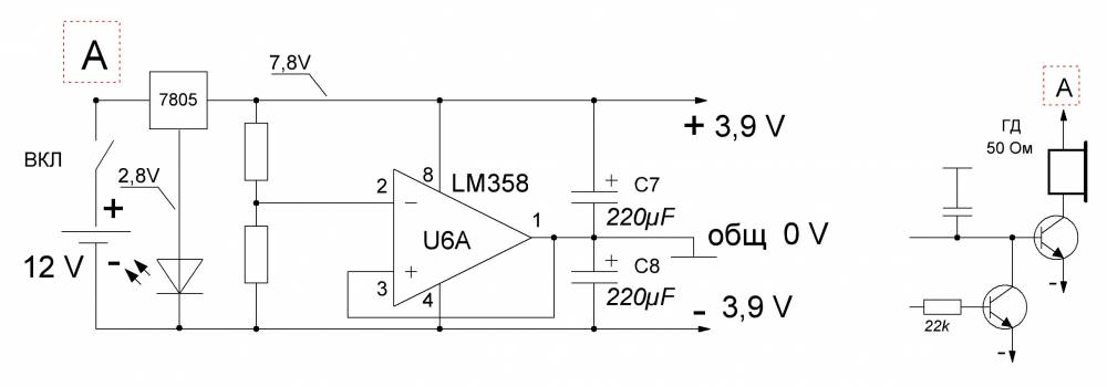
Metal detector power supply
Separately, the metal detector circuit draws 15-20 mA, with the coil connected + 30-40 mA, totaling up to 60 mA. Of course, depending on the type of speaker and LEDs used, this value may vary. The simplest case is that the power was taken from 3 (or even two) lithium-ion batteries connected in series from a 3.7V mobile phone and when charging discharged batteries, when we connect any 12-13V power supply, the charging current starts from 0.8A and drops to 50mA per an hour and then you don’t need to add anything at all, although a limiting resistor certainly wouldn’t hurt. In general, the simplest option is a 9V crown. But keep in mind that the metal detector will eat it in 2 hours. But for customization, this power option is just right. Under any circumstances, the crown will not produce a large current that could burn something on the board.
Homemade metal detector

And now a description of the process of assembling a metal detector from one of the visitors. Since the only instrument I have is a multimeter, I downloaded O.L. Zapisnykh’s virtual laboratory from the Internet. I assembled an adapter, a simple generator and ran the oscilloscope at idle. It seems to show some kind of picture. Then I started looking for radio components. Since signets are mostly laid out in the “lay” format, I downloaded “Sprint-Layout50”. I found out what laser-iron technology is for manufacturing printed circuit boards and how to etch them. Etched the board. By this time, all the microcircuits had been found. Whatever I couldn’t find in my shed, I had to buy. I started soldering jumpers, resistors, microcircuit sockets, and quartz from a Chinese alarm clock onto the board. Periodically checking the resistance on the power buses to ensure there are no snot. I decided to start by assembling the digital part of the device, as it would be the easiest. That is, a generator, a divider and a commutator. Collected. I installed a generator chip (K561LA7) and a divider (K561TM2). Used ear chips, torn out from some circuit boards found in a shed. I applied 12V power while monitoring the current consumption using an ammeter, and the 561TM2 became warm. Replaced 561TM2, applied power - zero emotions. I measure the voltage on the generator legs - 12V on legs 1 and 2. I am changing 561LA7. I turn it on - at the output of the divider, on the 13th leg there is generation (I observe it on a virtual oscilloscope)! The picture is really not that great, but in the absence of a normal oscilloscope it will do. But there is nothing on legs 1, 2 and 12. This means the generator is working, you need to change TM2. I installed a third divider chip - there is beauty on all outputs! I came to the conclusion that you need to desolder the microcircuits as carefully as possible! This completes the first step of construction.
Now we set up the metal detector board. The "SENS" sensitivity regulator did not work, I had to throw out the capacitor C3 after that the sensitivity adjustment worked as it should. I didn’t like the sound that appeared in the extreme left position of the “THRESH” regulator - threshold, I got rid of it by replacing resistor R9 with a chain of series-connected 5.6 kOhm resistor + 47.0 μF capacitor (negative terminal of the capacitor on the transistor side). While there is no LF353 microcircuit, I installed the LM358 instead; with it, Soviet three kopecks can be sensed in the air at a distance of 15 centimeters.

I turned on the search coil for transmission as a series oscillatory circuit, and for reception as a parallel oscillatory circuit. I set up the transmitting coil first, connected the assembled sensor structure to the metal detector, an oscilloscope parallel to the coil, and selected capacitors based on the maximum amplitude. After this, I connected the oscilloscope to the receiving coil and selected the capacitors for RX based on the maximum amplitude. Setting the circuits to resonance takes several minutes if you have an oscilloscope. My TX and RX windings each contain 100 turns of wire with a diameter of 0.4. We start mixing on the table, without the body. Just to have two hoops with wires. And to make sure of the functionality and possibility of mixing in general, we will separate the coils from each other by half a meter. Then it will be zero for sure. Then, having overlapped the coils by about 1 cm (like wedding rings), move and push apart. The zero point can be quite accurate and it is not easy to catch it right away. But it is there.
When I raised the gain in the RX path of the MD, it began to work unstably at maximum sensitivity, this was manifested in the fact that after passing over the target and detecting it, a signal was issued, but it continued even after there was no target in front of the search coil, this manifested itself in the form of intermittent and fluctuating sound signals. Using an oscilloscope, the reason for this was discovered: when the speaker is operating and the supply voltage drops slightly, “zero” goes away and the MD circuit goes into a self-oscillating mode, which can only be exited by coarsening the sound signal threshold. This didn’t suit me, so I installed a KR142EN5A + super bright white LED for power supply to raise the voltage at the output of the integrated stabilizer; I didn’t have a stabilizer for a higher voltage. This LED can even be used to illuminate the search coil. I connected the speaker to the stabilizer, after that the MD immediately became very obedient, everything started working as it should. I think the Volksturm is truly the best homemade metal detector!
Recently, this modification scheme was proposed, which would turn the Volksturm S into the Volksturm SS + GEB. Now the device will have a good discriminator as well as metal selectivity and ground detuning; the device is soldered on a separate board and connected instead of capacitors C5 and C4. The revision scheme is also in the archive. Special thanks for the information on assembling and setting up the metal detector to everyone who took part in the discussion and modernization of the circuit; Elektrodych, fez, xxx, slavake, ew2bw, redkii and other fellow radio amateurs especially helped in preparing the material.
Metal detectors or metal detectors are a diverse family of measuring instruments, the operation of which is based on differences in the electromagnetic radiation of objects.
Using a metal detector
Professional highly sensitive metal detectors are used in the daily work of various inspection points; they are used to conduct search and investigative activities of police and rescue services.

A huge army of amateur treasure hunters around the world practice long and leisurely hikes with metal detectors. Sometimes such entertainment brings income and even fame.

Nowadays, an industry of detector (recognition) devices has already been established for all occasions, differing not only in operating principles, but also in a wide range of prices and technical characteristics.
Simple magnetic detectors
The operating principle of the simplest metal detector is based on electromagnetic induction - the device contains an electromagnetic coil, which, due to oscillations and distortions of its field, detects nearby electrically conductive and iron-magnetic materials, creating an audio or visual signal.

The first experience of assembling a metal detector at home can be the beginning of a serious hobby: new design solutions and even inventions in this field of applied radio electronics are not excluded even at the amateur level.

The diagram shows the structure of a simple low-frequency magnetic detector.

Hundreds of different designs are used in the production of metal detectors. In order to implement one of them yourself, you will need to make a printed circuit board with your own hands, purchase the necessary coils, transistors, resistors, capacitors, etc., and assemble the device.

Metal detector made from improvised means
Another option is to assemble a metal detector from available materials; it is more suitable for humanists and novice technicians with a passion for finding treasures and lost artifacts.

During operation of such a homemade device, electromagnetic waves emitted by the calculator are caught on the AM band of the receiver.

An indicator of the location of an object in this device is the rotation of the electromagnetic field during re-emission, which changes the parameters of the sound signal. A photo of such a do-it-yourself metal detector can be found on the Internet and at the end of our material.

To use such a prefabricated version, you do not need a detailed diagram or assembly instructions, but compliance with certain requirements for the two main components of a homemade detector, namely a properly working calculator and a radio receiver.

Both devices must be from the cheapest category, the receiver must have an AM band and a magnetic antenna, and the calculator must emit pulsed radio interference during operation.

To work on the model, you will also need a suitable sized plastic box with an opening lid, like a book, which will become the body of the finder.

An old CD box is ideal for these purposes. To attach the parts you will need double-sided tape.

Metal detector assembly
- Securing the instruments inside the case: a strip of tape is attached to the back of the instruments, then the calculator is placed at the base of the box, the receiver is on the inside of the lid.
- Setting up the receiver: you need to turn on the receiver at maximum volume and select the upper position of the AM range, free from radio broadcasts and interference.
- Adjusting the calculator: when the calculator is turned on, the receiver should respond with a sharp noise, hum or wheezing; if this does not happen, you need to adjust the range.
- Fixing the position: we begin to smoothly close the box until the sound disappears or becomes more uniform and fix the box doors in this position, using a cube of foam plastic, rubber bands, etc.
- The metal detector is ready. If there is a product with electromagnetic radiation nearby, the receiver will sound an alarm.
By combining elements of other radio devices in a simple detector, you can observe the operating principle of metal detectors in action and enjoy your first search expedition.
Note!


Such a detector, assembled at home, can be tested to search for coins or metal construction debris lying in the surface layer of the earth in almost any area, on any open ground.

Photos of do-it-yourself metal detectors


Note!


Note!


Due to its electric or magnetic waves, a metal detector, or as it is also called a metal detector, is able to distinguish and respond to metal objects hidden in another environment. This device is an indispensable assistant for inspection services, environmentalists, builders, “gold miners” and many other specialties. The average price of a metal detector in the Russian Federation varies from 15-60 thousand rubles. This article is intended for those who do not want to overpay, want to understand the device themselves, and make a metal detector with their own hands.
Metal detector, its structure and principle of operation
The operating principle of a metal detector is complex only in words. Its essence lies in the formation of magnetic fields using electrical voltage, when these same waves encounter metal objects on their way, the device emits a signal, notifying about the find. For beginners who have not yet encountered such “inventions,” this seems quite difficult, but if you carefully follow the instructions, in reality everything will be much easier. And with a little understanding, you can easily create a device for finding an ancient coin at a depth of 30 cm underground.
Coil
In order to create a magnetic field, it is necessary for the current to pass through the riot ( bundle, winding) copper wire with nylon insulation. It is wound on a plastic spool several times. Then wrap with polyester, durable packing tape. This is necessary so that the wire cannot unwind back. If inside the reel ( special reel) place pure iron, the magnetic field will increase significantly, this method is usually used for security metal detectors.

Electronic circuit
The operation of the system depends entirely on the electronic circuit; this is the brain of the device. The remaining piece of copper wire is soldered to the printed circuit board, the other output of the board is connected by electrical wiring to sensors: LEDs, vibrators, speakers. In the event of a collision of magnetic waves with metal, an electrical signal will flow from the coil to the indicators through the board. This is perhaps the most difficult part of creating a device with your own hands. Then the device is calibrated, adjusted, and placed in a plastic protective case.
Main settings
Based on their properties, metal detectors are divided into 3 main groups: deep, underwater, and ground. From the name it is immediately clear what their features are. Although they often create hybrids, for example, in ground ones - a waterproof reel with a housing. Naturally, these will cost an order of magnitude higher. To make a metal detector yourself, you need to clearly understand for what purposes it will be used; based on this, there are general parameters of the device:
- Depth of action underground, each device has its own “penetration ability”. Of course, this also depends on the density, type of soil, and the presence of stones in it, but this is secondary.
- The diameter of the search zone, you must immediately determine for yourself which range will be optimal, and build on this when choosing or assembling a metal detector.
- Sensitivity of the metal device. Here the question arises for what purpose the device will be used: for treasure hunters, small things will only get in the way, but for hunters for lost jewelry on the beach, it is important not to miss anything, even the smallest thing.
- Metal selectivity. There are devices that only react to certain precious alloys.
- Power and energy saving are a standard feature of any wireless device.
- Brand new models have such a feature as “discriminability”, which allows you to display the approximate depth, location, and metal alloy on the device display.

Detection depth
On average, the search depth of a metal detector ranges from 1 to 100 centimeters. Different models have different accuracy and depth of action. Basically, the visibility range depends on the size of the coil, the larger it is, the deeper you can look. And the very first mistake of most beginners is, without knowing why, without knowing why, they choose a metal detector with the greatest depth of investigation. On average, ancient coins are buried 30-35 centimeters, and lost precious jewelry is even closer to the surface. In addition, the greater the depth, the more errors and errors. You can dig 10 holes 1 meter deep, and in the same time you can find something really valuable almost on the surface, without bothering at all.
Operating frequency
Like any device, a metal detector has an interconnection of its components. Using the device at full power, you increase the energy consumption of the battery. If we consider the metal detector as a whole, we can conclude that all its component dimensions and functionality depend on the frequency of the generator. This is perhaps the most important evaluation criterion by which they are classified:
- The first option is not at all amateur - ultra-low frequency. Without some computer support it will not be able to work. The coil must be followed by a special machine, which will not only process the signal to the operator, but also supply a charge, due to its considerable energy consumption. Its range is less than 100 Hz.
- The second option is also not a simple household appliance - a low-frequency one. The range varies from 100 Hz to 10 kHz. It also requires a lot of energy, and is mainly designed to search for ferrous metals up to 5 meters deep. Requires computer signal processing, but even with its help, it has a large error in recognizing the alloy and its volume at great depths.
- Universal, more complex, compact - high-frequency metal detectors. Using such a device you can find metal 1.5 meters deep. It has average noise immunity, but good sensitivity; at shallow depths, it is possible to determine the alloy and dimensions of the metal with fairly good accuracy. Has a range of up to 30 kHz.
- Radio frequency metal detectors, probably everyone has seen them, are a standard device suitable for aspiring hobbyists. Has excellent discrimination up to 0.5 meters deep. If the soil does not have magnetic properties, for example sand, or there is no radio or television station nearby, then this is simply an excellent universal device. Its energy consumption is very low compared to the representatives above. And its full effectiveness will also depend on its components, largely on the coil.
DIY metal detector assembly
There are a large number of diagrams, videos, forums, and tips on assembling a metal detector on the Internet. And among the many reviews, there are many negative ones about the device of its own production. Many write that it didn’t work out for them, it doesn’t work, that it’s better to buy than to spend a lot of time... It’s very simple to answer such comments: if you set a goal and approach the issue seriously, then production with your own hands will turn out to be much better than factory metal detectors. If you want to do something well, do it yourself.
Is it possible to make a metal detector with your own hands?
For a person who at least at school level knows and is interested in physics and electronics, such a task will not be difficult. And the matter will remain only with the selection of quality materials. But beginners should not retreat, step by step, following the instructions, adding a little persistence, everything will certainly work out.
Do-it-yourself printed circuit board manufacturing
The most difficult stage in detector assembly is the manufacture of the printed circuit board. Since this is the brain of the entire structure, and without it the device simply will not work. Let's start with the simplest manufacturing technology - Laser ironing.
- Initially, we will need a diagram; of course, there are a huge number of them on the Internet. But if a person sets out to do everything himself, a special program Sprint-Layout will come to the rescue, which will help you develop it.
And so, having a ready-made schematic drawing of the board, we print it using a laser printer, this is important, on photo paper. Many people recommend using light weight paper to bring out the details better. - Buy a piece of PCB, it won’t be difficult to find it, and prepare it properly:
1) Using metal scissors (or a metal knife) we cut out a blank from a piece of textolite according to the dimensions we need and the corresponding printout parameters.
2) Then you need to thoroughly clean the workpiece from the top layer using sandpaper. The ideal result is a uniform mirror shine.
3) Wet a piece of rag in alcohol, acetone, or another solvent, and wipe thoroughly. This is required in order to degrease and clean our workpiece material. - After the procedures have been completed, we place photo paper with a printed diagram on the textolite and smooth it with a hot iron so that the drawing is transferred. Then you should slowly immerse the workpiece in warm water, and very carefully and carefully, without smearing the design, remove the paper. But even if the contour is a little blurred, it doesn’t matter, you can correct it with a needle.
- When the board dries a little, the next stage begins, for which we need a solution of copper sulfate or ferric chloride.
To prepare this solution, you need to purchase ferric chloride powder (FeCl3). In a radio store it costs just a penny. We dilute this powder with water in a ratio of 1 to 3. The water should not be hot, and the dishes should not be made of metal.
We immerse our board in the solution for some time, depending on the thickness of the material and external conditions, there is no specific time. If you stir the solution periodically, the process will go faster and better. - We take out the board, wash it under running water, remove the toner with alcohol or any other solvent.
- Using a drill, we make holes for the parts where they are needed according to the diagram.
More details about this method can be found in our article:
Installation of radio components on the board
At this stage, it is necessary to equip the board with all the necessary radio components. Don’t be afraid of complex names or unknown combinations of numbers and letters. All details are signed. You just need to find the right ones, buy them, and install them in your place.

Here is an example of a fairly simple but effective scheme - PIRATE
So, let's begin:
- As the main microcircuit, it is quite possible to take the inexpensive KR1006VI1, or its various foreign analogues, for example, NE555, it is used in the diagram provided above. To install the circuit on the board, you need to solder a jumper between them.
- The next step is to install an amplifier, for example K157UD2, which is also shown in the diagram above. By the way, by rummaging through old Soviet instruments you can find this and many other details.
- Then we install two SMD components (they look like small bricks) and mount the MLT C2-23 resistor.
- Having installed the resistor, you need to stop the two transistors. A very important point for beginners: the structure of the first must correspond to NPN, and the other to PNP. BC 557 and BC 547 are ideal for this device, but since they are not so easy to find, various foreign analogues can be used. But the field-effect transistor is IRF-740, or any other one with the same parameters; in this case it doesn’t matter.
- The last step will be the installation of capacitors. And just a piece of advice: it is best to choose one with the lowest TKE value, this significantly improves thermoregulation.
Making a coil
As already written earlier, when making a homemade coil, you need to wind approximately 25-30 turns of PEV wire if its diameter is 0.5 millimeters. But it is best, when testing the device in action, to select and change the number of turns to achieve the desired result.
Frame and additional elements
To recognize the device's discovery, you can use any speaker with a resistance of zero ohms. As a power supply, you can use a battery or simple batteries with a total voltage of more than 13 volts. For greater stability and electrical balance of the circuit, a stabilizer is mounted at the output. For a pirate circuit, the ideal voltage type would be L7812.
Once we are convinced that the metal detector is working, we turn on our imagination and create a frame that will be primarily convenient for the operator. There are some practical tips for creating a case:
- The board must be protected by placing it in a special box, firmly securing it in a stationary state. We place the box itself on the frame for convenience.
- When creating a housing, one point must be taken into account: the more metal objects are present in the design, the less sensitive the device will become.
- To provide the device with all sorts of amenities, such as an armrest, you can use a piece of sawn water pipe in half. Attach a rubber handle below. And at the very top part, build some kind of additional holder.
Diagrams of the most popular metal detectors
Butterfly scheme

Koschey scheme

Quasar scheme

Chance Scheme

Many people unreasonably believe that homemade metal detectors are inferior in many respects to branded samples produced at the factory.
But in fact, structures that are correctly assembled with your own hands sometimes turn out to be not only better, but also cheaper than “factory” competitors.
Worth knowing: Most treasure hunters and local historians, in order to save money, try to choose the cheapest options. As a result, they either assemble metal detectors themselves or purchase homemade custom devices.
Beginners, as well as people who do not understand electronics, are at first intimidated by the abundance of not only special terminology, but also various formulas and circuits. However, if you delve a little deeper, everything immediately becomes clear, even with the knowledge gained in school physics lessons.
Therefore, it is worth, first of all, to understand the principle of operation of a metal detector, what it is and how you can assemble it yourself at home.
How does it work
The operating principle of this device is to use an electromagnetic field. It is created by the transmitter coil and after a collision with an object that conducts current (which is most metals), eddy currents are created that introduce distortion into the EPM of the coil.
In cases where the object is not electrically conductive, but has its own magnetic field, the interference it creates will also be captured due to shielding.
After this, changes in the electromagnetic field are sent directly to the control unit, which emits a special sound signal to notify that a person has been found, and in more expensive models displays data on the display.
It is worth examining how such devices are created following the example of a “Pirate” type metal detector.

Metal detector "Pirate"
Making a printed circuit board with your own hands
First you need to create a printed circuit board, where all the nodes of the metal detector will be located in the future. The best method is laser-iron technology or simply LUT.
To do this, it will be necessary to perform the manufacturing steps in the following sequence:
- First, using only a laser printer, you need to print the corresponding diagram created through the Sprint-Layout program. It is best to use light weight photo paper for this.
- We prepare the PCB workpiece, first sand it, and then clean it with a solution. It should have dimensions 84x31.
- Now on top of the blank we place photo paper with the diagram on the front side on which it was printed. Cover with an A4 sheet and begin ironing with a hot iron in order to transfer the marking scheme to the textolite.
- After fixing the circuit from the toner, we place it all in water, where we carefully remove the paper with our fingers.
- Next, if there are smeared areas, we correct them using a regular needle.
- Now the board needs to be placed in a solution of copper sulfate for several hours (ferric chloride can also be used).
- The toner can be removed without any problems with any solvent, such as acetone.
- We drill holes for later placement of structural elements (the drill must be very thin).
- The last stage is to lay out the board tracks. To do this, a special solution “LTI-120” is smeared on the surface, which needs to be spread over the solder of the soldering iron.
Installing elements on the board
 This stage of creating a metal detector consists of installing all the elements on the created board:
- The main microcircuit is the domestic KR1006VI1 or its foreign analogue NE555. Please note that before installation, a jumper must be soldered underneath it.
- Next, a two-channel amplifier K157UD2 is installed. You can buy it or take it from Soviet tape recorders.
- After this, 2 SMD capacitors are mounted, as well as one resistor of the MLT C2-23 type.
- Now you need to solder two transistors. One must be NPN structure, and the other PNP. It is advisable to use BC557 and BC547. However, analogues will also work. It is recommended to use IRF-740 or other options with similar characteristics as a field-effect transistor.
- The capacitors are installed last. They should be taken with a minimum TKE indicator, which will increase the thermal stability of the entire structure.
Note: The hardest thing will be to get the K157UD2 amplifier out of this circuit. The reason is that it is already an old chip. That is why you can try to find similar modern options with similar parameters.

A homemade coil is created on a frame with a diameter of 20 cm. The total number of turns should be approximately 25 pieces. This indicator is based on the fact that PEV wire is used, which has a diameter of 0.5 mm.
However, there is a certain peculiarity. The total number of turns can be changed up or down. To find the most optimal option, you need to take a coin and check in which case there will be the longest distance to “catch” it.
Other elements
A signal speaker can be used taken from a portable radio. It is important that it has a resistance of 8 ohms (Chinese options can be used).

To carry out the adjustment, you will need two potentiometer models of different power: the first is 10 kOhm, and the second is 100 kOhm. To minimize the influence of interference (it will be difficult to eliminate it completely), it is recommended to use a shielded wire that will connect the circuit and the coil. The metal detector's power source must be at least 12 V.

 When the entire structure has been tested for functionality, it is necessary to make a frame for the future metal detector. However, here we can only give some recommendations, because everyone will create it from the items at hand:
- to make the bar more convenient, it is worth purchasing 5 meters of ordinary PVC pipe (which are used in plumbing), as well as several jumpers. It is worth installing a special palm rest at its upper end to make it more comfortable to hold. For the board, you can find any box of the appropriate size that needs to be mounted on the rod;
- To power the system, you can use a battery from a regular screwdriver. Its advantages are low weight and high capacity;
- When creating the body and structure, keep in mind that there should not be any unnecessary metal elements in them. The reason is that they significantly distort the resulting electromagnetic field of the future device.
Checking the metal detector
 First of all, you need to adjust the sensitivity using potentiometers. The threshold will be a uniform, but not very frequent, crackling.
So, he will have to “find” a five-ruble coin from a distance of approximately 30 cm, but if the coin is the size of a Soviet ruble, then from about 40 cm. He will “see” large and voluminous metal from a distance of more than a meter.
Such a device will not be able to search for small objects at significant depths. In addition, he will not be able to distinguish between the size and type of metal found. That is why, while searching for coins, you may come across ordinary nails.
This model of homemade metal detector is suitable for people who are just starting to learn the basics of treasure hunting or do not have the necessary funds to purchase an expensive device.
Their this video You will learn how to make a homemade metal detector: